Honda Civic Service Manual: M/T Shift Fork Clearance Inspection (K24Z7)

Removal
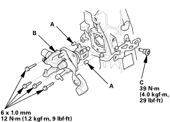
| 1. | M/T Change Lever Assembly |
|
|
|
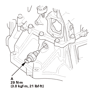
| 2. | Back-Up Light Switch |
|
|
|
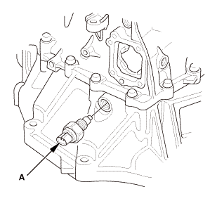
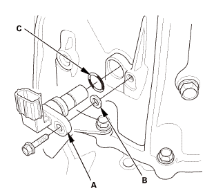
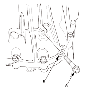
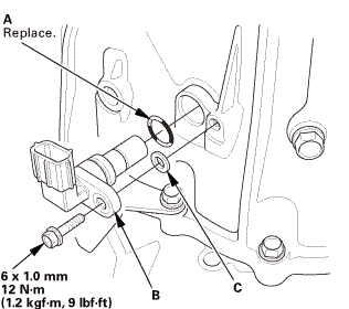
| 3. | Output Shaft (Countershaft) Speed Sensor |
|
|
|
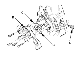
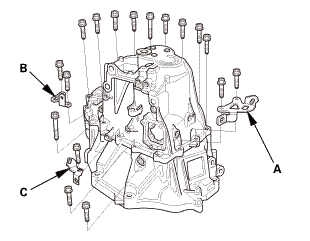
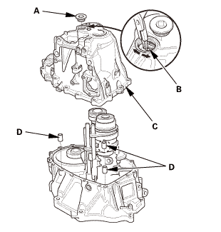
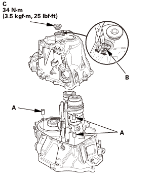
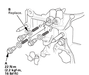
| 4. | Transmission Housing |
|
|
|
|
|
|
|
|
|
|
|
|
 Inspection
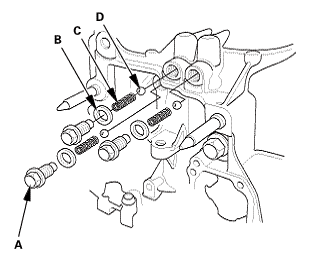
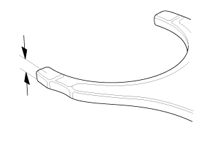
| 1. | Shift Fork Clearance Inspection |
|
|
|
||||||||||||
|
|
|
|||||||||||||||||||||||||

|
|
|
||||||||||||
|
|
|
|||||||||||||||||||||

Installation
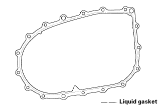
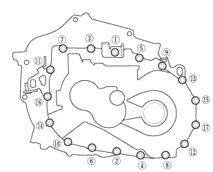
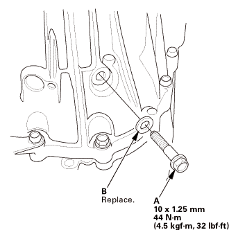
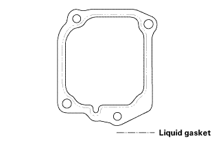
| 1. | Transmission Housing |
|
|
|
||||||||||||||||||||
|
|
|
|||||||||||||||
|
|
|
|||||||||||||||||||||||
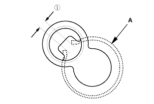
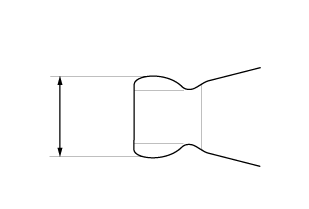
 as installed:
3.3-6.0 mm (0.130-0.236 in)
as installed:
3.3-6.0 mm (0.130-0.236 in)|
|
|
|
|
|
||||||||||
|
|
|
|
|
|
| 2. | Output Shaft (Countershaft) Speed Sensor |
|
|
|
| 3. | Back-Up Light Switch |
|
|
|
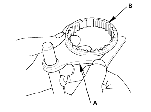
| 4. | M/T Change Lever Assembly |
|
|
|
||||||||||||||||||||
 iukn
iukn|
|
|
 M/T Reverse Shift Fork Clearance Inspection (R18Z1 M/T)
Removal
1.
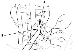
M/T Change Lever Assembly
1.
Remove the change lever assembly (A).
...
 M/T Shift Fork Disassembly and Reassembly (K24Z7)
View
NOTE: Prior to reassembling, clean all parts in solvent, dry them, and
apply MTF to any contact surfaces.
1.
M/T Shift Fork Exploded View
...
See also:
Honda Civic Owners Manual. Manual transmission models
Shift Lever Operation
Fully depress the clutch pedal to operate the shift lever and change gears,
then
slowly release the pedal.
Depress the clutch pedal, and pause for a few seconds before shifting into R, or
shift into one of the forward gears for a moment. This stops the gears so they
d ...
