Honda Civic Service Manual: M/T Mainshaft Assembly Clearance Inspection (K24Z7)

Removal
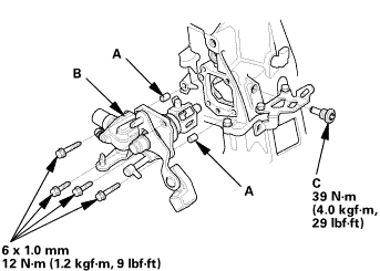
| 1. | M/T Change Lever Assembly |
|
|
|
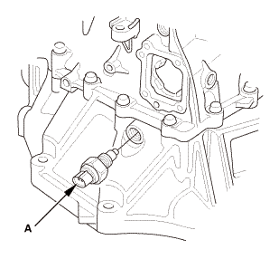
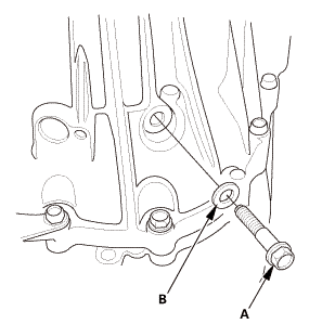
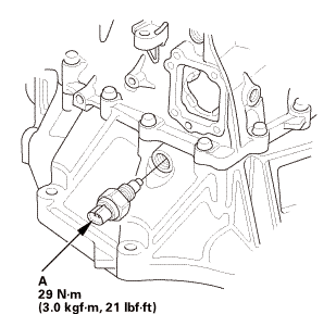
| 2. | Back-Up Light Switch |
|
|
|
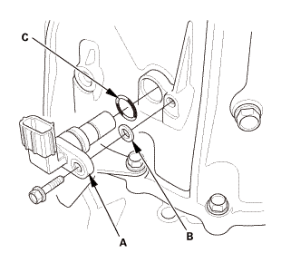
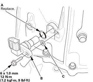
| 3. | Output Shaft (Countershaft) Speed Sensor |
|
|
|
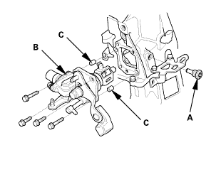
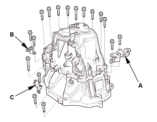
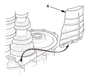
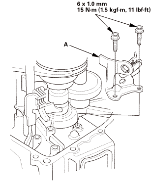
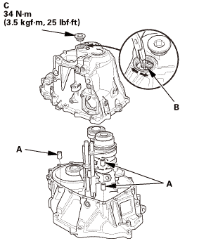
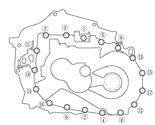
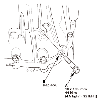
| 4. | Transmission Housing |
|
|
|
|
|
|
|
|
|
|
|
|
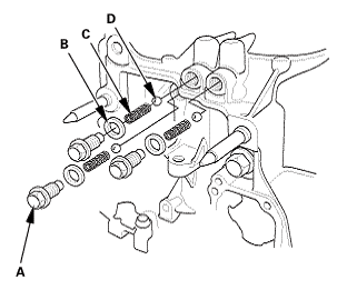
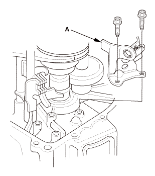
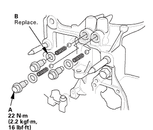
| 5. | Reverse Shift Fork |
|
|
|
| 6. | Baffle Plate |
|
|
|
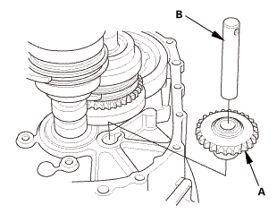
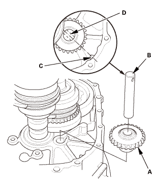
| 7. | Reverse Idler Gear |
|
|
|
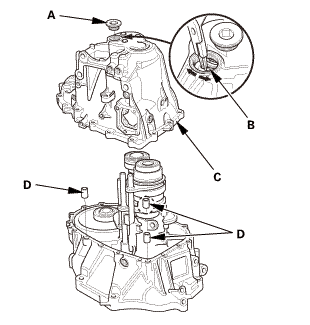
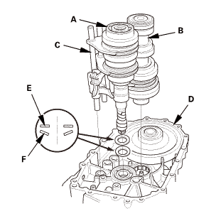
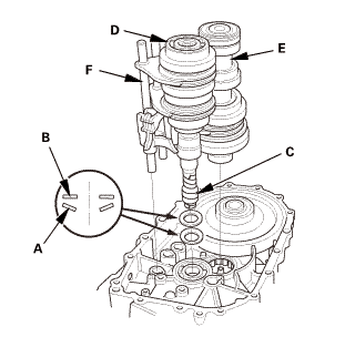
| 8. | M/T Mainshaft and Countershaft and Shift Fork Assembly |
|
|
|
|||||||||||||||
 Inspection
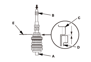
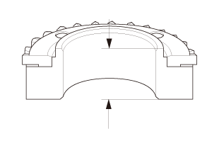
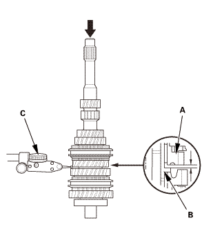
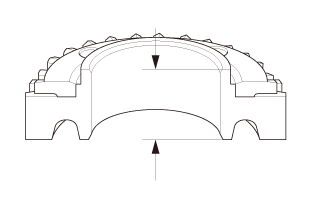
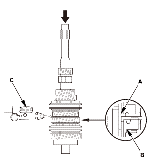
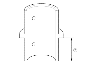
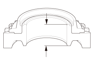
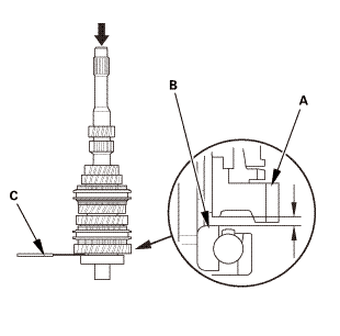
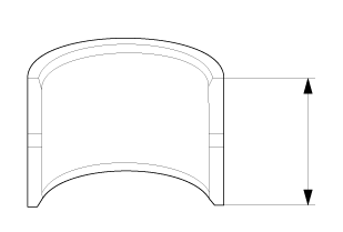
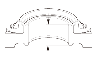
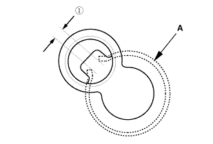
| 1. | Mainshaft Assembly Clearance Inspection |
|
|
|
||||||||||||||||||||||||||

|
|
|
|||||||||||||||||||||||
|
|
|
|||||||||||||||||||||||
|
|
|
|||||||||||||||||||||
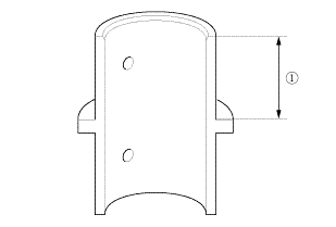
 of the 4th/5th
gear distance collar as shown.
of the 4th/5th
gear distance collar as shown.|
|
|
|||||||||||||||||||||||
|
|
|
|||||||||||||||||||||||
|
|
|
|||||||||||||||||||||
 of the 4th/5th
gear distance collar as shown.
of the 4th/5th
gear distance collar as shown.|
|
|
|||||||||||||||||||||||
|
|
|
||||||||||||
|
|
|
|||||||||||||||||||||
|
|
|
|||||||||||||||||||||||

Installation
| 1. | M/T Mainshaft and Countershaft and Shift Fork Assembly |
|
|
|
||||||||||||||||||
| 2. | Reverse Idler Gear |
|
|
|
| 3. | Baffle Plate |
|
|
|
| 4. | Reverse Shift Fork |
|
|
|
 mmlbf!
| 5. | Transmission Housing |
|
|
|
||||||||||||||||||||
|
|
|
|||||||||||||||
|
|
|
|||||||||||||||||||||||
|
|
|
|
|
|
||||||||||
|
|
|
|
|
|
| 6. | Output Shaft (Countershaft) Speed Sensor |
|
|
|
| 7. | Back-Up Light Switch |
|
|
|
| 8. | M/T Change Lever Assembly |
|
|
|
||||||||||||||||||||
 iukn
iukn|
|
|
 M/T Countershaft Disassembly, Reassembly, and Inspection (K24Z7)
Disassembly
NOTE: Refer to the Exploded View as needed during this procedure.
1.
M/T Change Lever Assembly
...
 M/T Mainshaft Assembly Clearance Inspection (R18Z1 M/T)
Disassembly
1.
M/T Change Lever Assembly
1.
Remove the change lever assembly (A).
...
See also:
Honda Civic Owners Manual. How to Select a Play Mode
You can select shuffle and repeat modes when playing a file.
Select a play mode.
To turn off a play mode
Select the mode you want to turn off.
How to Select a Play Mode
Play Mode Menu Items
Shuffle All Songs: Plays all available files in a
selected list (playlists, artists, albums, song ...
