Honda Civic Service Manual: Clutch Master Cylinder Removal and Installation (R18Z1 M/T)
211101

|
NOTE: |
|
|||
|
|||
|
|||
|

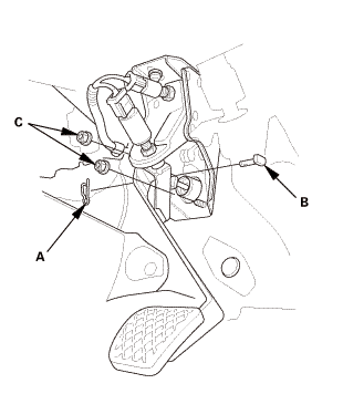
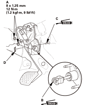
| 1. | Clutch Pedal |
|
|
|
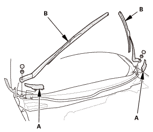
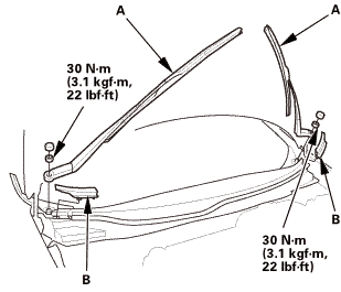
| 2. | Wiper Arm Assembly |
|
|
|
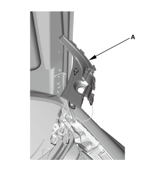
| 3. | Both Side Cowl Covers |
|
|
|
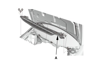
| 4. | Center Cowl Cover |
|
|
|

| 5. | Under Cowl Panel |
|
|
|
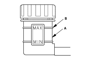
| 6. | Clutch Fluid |
|
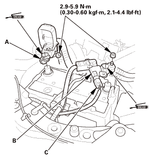
| 7. | Battery Terminal - Disconnection |
|
|
|
|||||||||||||||||||||||||||
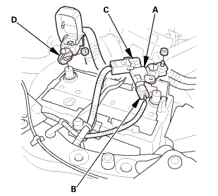
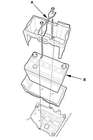
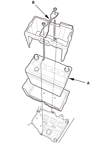
| 8. | Battery |
|
|
|
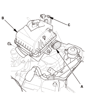
| 9. | Intake Air Pipe |
|
|
|
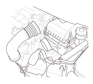
| 10. | Air Cleaner |
|
|
|
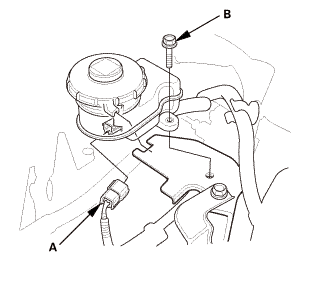
| 11. | Brake Reservoir Tank |
|
|
|
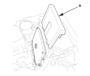
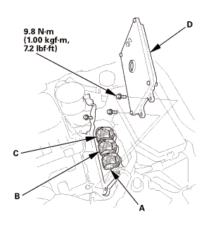
| 12. | ECM/PCM |
|
|
|
|
|
|
|||||||||
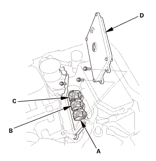
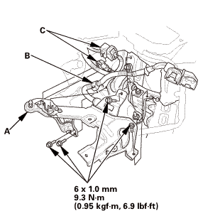
| 13. | Air Cleaner Bracket |
|
|
|
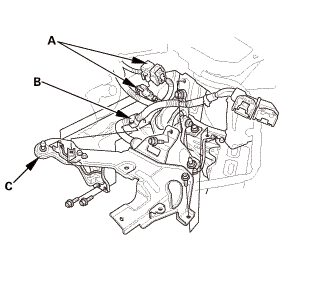
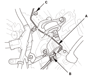
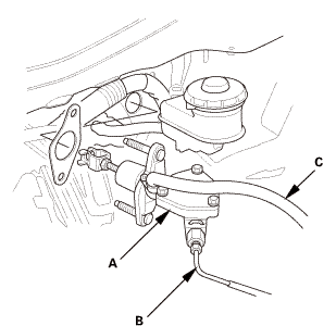
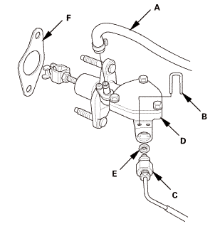
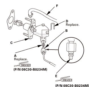
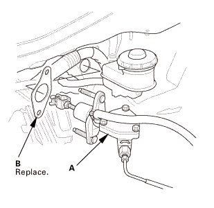
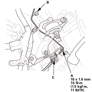
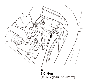
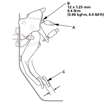
| 14. | Clutch Master Cylinder |
|
|
|
|
|
|
|
|
|
|||||||||||||||

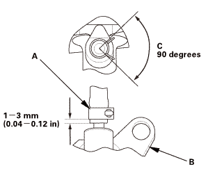
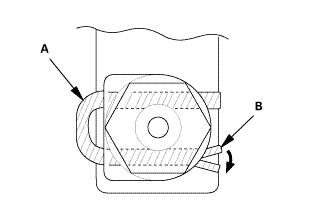
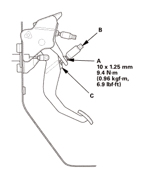
| 1. | Clutch Master Cylinder Push Rod Inspection |
|
|
|
||||||
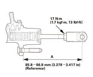 17inasmm
| 2. | Clutch Master Cylinder |
|
|
|
|||||||||||||||||||||||
|
|
|
||||||
|
|
|
|
|
|
|
|
|
 us
us| 3. | Clutch Pedal |
|
|
|
||||||||||||||||||
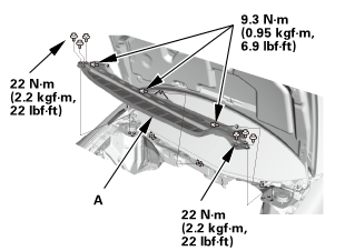
| 4. | Under Cowl Panel |
|
|
|
 22mm)2222
| 5. | Center Cowl Cover |
|
|
|
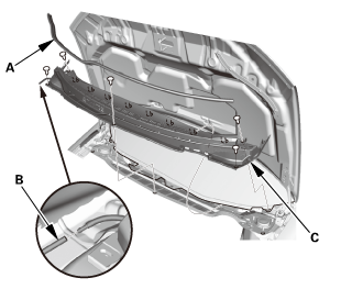
| 6. | Both Side Cowl Covers |
|
|
|
| 7. | Wiper Arm Assembly |
|
|
|
 1.122
1.122| 8. | Clutch Fluid |
|
| 9. | Clutch Fluid Bleeding |
|
|
|
|
|
|
|||||||||||||||||||||||||||||||||
| 10. | Air Cleaner Bracket |
|
|
|
| 11. | ECM/PCM |
|
|
|
|||||||||
|
|
|
| 12. | Brake Reservoir Tank |
|
|
|
 nomm
nomm| 13. | Air Cleaner |
|
|
|
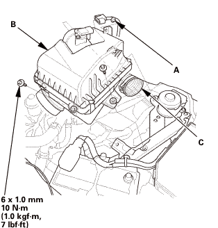
| 14. | Intake Air Pipe |
|
|
|
| 15. | Battery |
|
|
|
||||||
| 16. | Battery Terminal - Reconnection |
|
|
|
|||||||||||||||||||
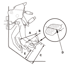
| 17. | Clutch Pedal Stroke Check |
|
|
|
|
|
|
||||||||||||||||||||||||||||||||||||
| 18. | HDS DLC - Connection |
|
|
|
| 19. | Clutch Pedal Position Switch A Adjustment |
|
|
|
||||||||||||||||||||||||
| 20. | Clutch Operation Check |
|
| 21. | Test Drive |
|
 Clutch Master Cylinder Removal and Installation (K24Z7)
2111C5
NOTE:
Use fender covers to avoid damaging painted surfaces.
...
 Clutch Pedal Assembly Removal and Installation (M/T)
2111A0
1.
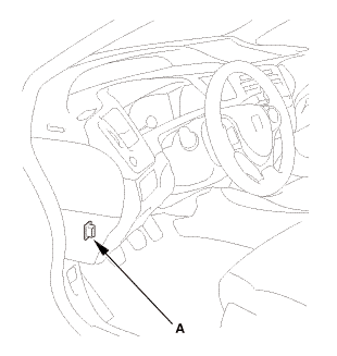
Clutch Pedal Position Switch Connector
1.
Disconnect the connectors.
...
See also:
Honda Civic Owners Manual. Precautions for Opening/Closing the Trunk
Opening the trunk
Open the trunk all the way.
If it is not fully opened, the trunk lid may begin to close under its
own weight.
Closing the trunk
Keep the trunk lid closed while driving to:
Avoid possible damage.
Prevent exhaust gas from leaking into the vehicle.
Exhaust Gas Haz ...
