|

|
If an accidental system discharge occurs, ventilate the work
area before resuming service.
|
|
|
|
Additional health and safety information may be obtained from
the refrigerant and lubricant manufacturers.
|
|
|
|
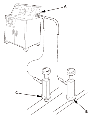
Check the system for leaks using an R-134a refrigerant leak detector
with an accuracy of 14 g (0.5 oz) per year or better.
|
|
|
|
Do not install an A/C compressor into a system unless you are
completely sure that the system is free of contamination. Installing
the A/C compressor into a contaminated system can result in premature
A/C compressor failure.
|
|
|
|
Inspect the A/C lines for any signs of contamination.
|
|
|
|
If you're installing a new A/C compressor, you must calculate
the amount of refrigerant oil to be removed from it. A new A/C compressor
comes with a full charge of oil.
|
|
|
|
Replace the O-rings with new ones at each fitting, and apply
a thin coat of refrigerant oil before installing them. Be sure to
use the correct O-rings for HFC-134a (R-134a) to avoid leakage.
|
|
|
|
Use only PAG refrigerant oil (SP-10) for HFC-134a A/C systems.
|
|
|
|
To avoid contamination, do not return the oil to the container
once dispensed, and never mix it with other refrigerant oils.
|
|
|
|
Immediately after using the oil, reinstall the cap on the container,
and seal it to avoid moisture absorption.
|
|
|
|
Do not spill the refrigerant oil on the vehicle; it may damage
the paint; if the refrigerant oil contacts the paint, wash it off
immediately.
|
|
|
|
Be careful not to damage the radiator fins when installing the
A/C compressor, the alternator or the A/C condenser fan shroud.
|
|
|
|
Position the vehicle in a wind-free work area. This will aid
in detecting small leaks.
|
|
|
|
When using the leak detector for the first time, allow it to
warm up for 2 minutes with the probe in a clean atmosphere. This
lets the temperature sensor in the detector stabilize.
|
|
|
|
The calibration check should be done in the ‘‘Search 2’’
mode. Once that is done, the other check modes do not need calibrating.
|
|
|
|
When leak checking through the HVAC module drain hose, avoid
drawing water into the probe. Water can damage the internal pump
and sensor.
|
|
|
|
Avoid creasing the flexible probe extension. Creases can restrict
air flow and give false readings.
|
|
|
|
Because the detector recalibrates itself for ambient gases, it
may be necessary to move the detector away from the leak to clear
the sensor. Once the sensor has cleared, recheck the suspected leak.
|
|
|
|
When removing the clear probe tip, be careful not to lose the
flow ball.
|
|
|
|
R-134a is heavier than air; always check below and to the sides
of all potential leak sources.
|
|
|
|
Halogen leak detectors are sensitive to chemicals: windshield
washing solutions, solvents/cleaners, and some vehicle adhesives.
Keep these chemicals out of the area when doing leak detection.
|
|
|
|
Use only Tracer-Stick single dose fluorescent dye capsules from
Tracerline®. Other dyes contain solvents that may contaminate the
refrigerant oil, leading to component failure.
|
|
|
|
Adding excessive amounts of dye can damage the A/C compressor.
|
|
|
|
PAG oil is water soluble, so condensation on the evaporator core
or the refrigerant lines may wash the PAG oil and fluorescent dye
away from the actual leak. Condensation may also carry dye through
the HVAC module drain.
|
|
|
|
After checking and repairing leaks, thoroughly clean any residual
dye from the areas where leaks were found. Use GLO-AWAY dye cleaner,
from Tracerline®, and hot water to remove the dye (follow the instructions
on the bottle). Residual dye stains can cause misdiagnosis of any
future A/C system leaks.
|
|
|
|
If any refrigerant dye contacts an exterior paint surface, remove
it by doing this:
|
|
|
-
|
Carefully wash the affected surfaces to remove any dirt,
and to prevent paint scratching.
|
|
|
-
|
Mix water and isopropyl alcohol in a 50/50 mixture. Soak
a soft 100 % cotton towel with the water/alcohol mixture,
and place the cloth on the affected areas to remove the
dye.
|
|
|
-
|
After removing the dye with the water/alcohol-soaked
cloth, carefully wash the affected areas, and check that
there is no remaining dye.
|
|
|
|
1.
|
With the engine OFF, use a halogen leak detector first to detect the
leak source. Follow a continuous path in order to ensure that you will not
miss any possible leaks. Test the following areas of the system for leaks:
|
|
|
Possible Leak Area
|
Diagnostic Procedure with the Leak Detector
|
Notes
|
|
Service ports
|
|
|
Check the service ports with caps installed
|
|
|
|
If the detector ‘‘sniffs’’ a
leak, use fluorescent dye to confirm it
|
|
|
When capping the service ports, ensure that the seals
on the port caps are in place, and that the caps are tight.
The caps are used as the final seals in the system
|
|
A/C condenser
|
If the detector ‘‘sniffs’’ a leak, use fluorescent
dye to confirm it
|
|
|
Check for joints or connections coated
with oily dust
|
|
|
|
Check for damaged and corroded areas
|
|
|
|
Check all fittings, couplings, brazed/welded
areas and areas around attachment points
|
|
|
|
Move the probe slowly (1 in/second or
less), and keep it within 1/4 in of the
component being checked. This maximizes
the chance of detecting a leak
|
|
|
|
If you detect a leak, blow compressed
air over the area, then recheck for leaks.
For large leaks, clearing the area with
compressed air may help you pinpoint the
leak source
|
|
|
|
Evaporator
|
|
|
Check at the evaporator drain hose
|
|
|
|
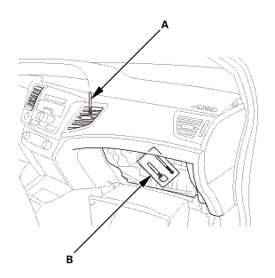
Check at the passenger's side vent and
turn the blower on low speed
|
|
|
|
|
A/C lines
|
|
|
Wiggle the rubber hoses when checking
crimped metal ends
|
|
|
|
If the detector ‘‘sniffs’’ a
leak, use fluorescent dye to confirm it
|
|
|
|
|
Check all fittings, couplings, pressure
switches, brazed/welded areas, and areas
around attachment points on A/C lines and
components
|
|
|
|
Check for damaged and corroded areas
|
|
|
|
Move the probe slowly (1 in/second or
less), and keep it within 1/4 in of the
component being checked. This maximizes
the chance of detecting a leak
|
|
|
|
|
|
|
8.
|
Run the engine and A/C system for 15 minutes to thoroughly circulate
the dye. Then shut the engine off, and inspect the following areas of the
system for leaks:
|
|
NOTE:
|
|
|
Check for leaks in a dark work area, and use the UV light
and the special glasses from the leak check kit. Other UV
lights may not work well with the Tracer-Stick® dye.
|
|
|
|
Small leaks may take up to 1 week of vehicle operation
(with normal A/C use) to become visible.
|
|
|
|
|
Possible Leak Area
|
Diagnostic Procedure with Fluorescent Dye
|
|
Service ports
|
If a leak is found, replace the cap/O-ring seal or A/C
line as needed
|
|
A/C lines
|
|
|
Use a permanent marker pen to circle
the leak area
|
|
|
|
If a leak is found, remove and replace
the A/C line
|
|
|
|
A/C condenser
|
|
|
If a leak is found, remove the A/C condenser
|
|
|
|
Determine whether leak is in the A/C
condenser or the receiver/dryer
|
|
|
|
Use a permanent marker pen to circle
the leak area
|
|
|
|
Replace either the receiver/dryer, or
the A/C condenser, depending upon which
is leaking
|
|
|
|
A/C compressor
|
|
|
Check for leaks at all of the A/C compressor
joints, the clutch center, the A/C compressor
front housing bolts, and the scroll bolts
on the back of the A/C compressor
|
|
|
|
If a leak is found, use a permanent marker
pen to circle the leak area
|
|
|
|
If the A/C compressor relief valve appears
to be leaking, determine whether the leak
is coming from the relief valve, or the
joint between the A/C compressor casing
and the valve. If the leak is from the relief
valve, check the A/C system pressures, and
refer to the pressure test table in the
A/C system test. If the leak is from the
casing/valve joint, replace the A/C compressor
relief valve
|
|
|
|
If the leak is coming from the suction
hose and/or discharge hose fittings on the
A/C compressor, clean the A/C fittings and
replace the suction/discharge fitting O-rings
|
|
|
|
For all other A/C compressor leaks, remove
and replace the A/C compressor
|
|
|
|
Evaporator
|
|
|
Start checking for evaporator leaks by
illuminating the evaporator drain tube area
|
|
|
|
If a leak is found, remove the evaporator
core
|
|
|
|
Determine whether leak is from evaporator
or expansion valve
|
|
|
|
Use a permanent marker pen to circle
leak area
|
|
|
|
Replace the expansion valve, or the evaporator
core, depending upon which is leaking
|
|
|
|
|
|
See also:
Honda Civic Owners Manual. Windshield Wiper/Washer
The windshield wipers and washers can be
used when the ignition switch is in ON
*1.
MIST
The wipers run at high speed until you release
the lever.
Wiper switch (OFF, INT*2/AUTO*3, LO,
HI)
Move the lever up or down to change the
wiper settings.
Adjusting wiper operation*
Turn the adjus ...


 vnm
vnm

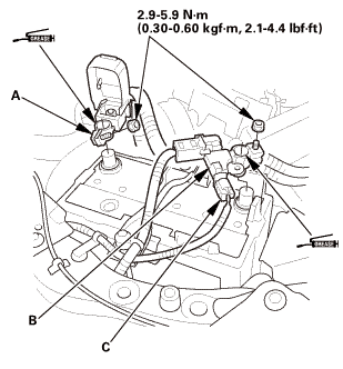
 x12emm22(2um
 lnmm(mam,7.2lbf!
 vnm
vnm

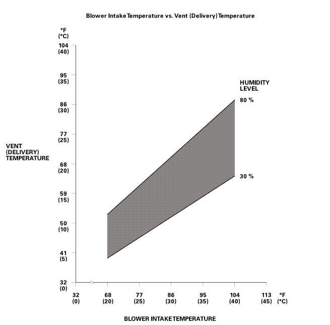 orhuullnrrvlevel11vmrsono):277-rin)ian)amwinintaketemperature
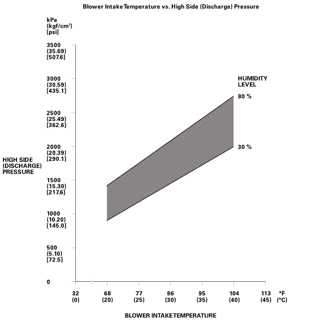 sun:highnuwuomlevel2217-s
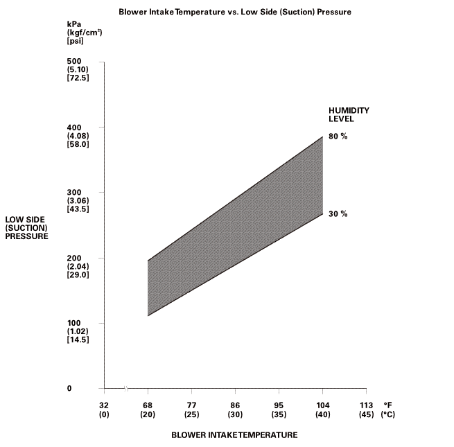 turn(suction)snnhuuunrrvlevel(sucnomzoo(am[am77-r(ulam
 A/C Compressor Removal and Installation (Except K24Z7)
 A/C Compressor Thermal Protector Removal and Installation (K24Z7)