Honda Civic Service Manual: VTC Actuator Inspection (K24Z7)

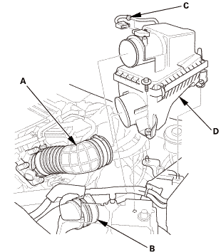
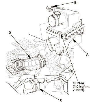
| 1. | Air Cleaner Assembly |
|
|
|
| 2. | Vehicle Lift |
|
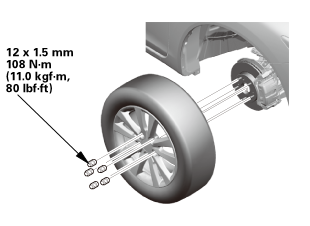
| 3. | Tire and Wheel-Removal, Front Right |
|
|
|
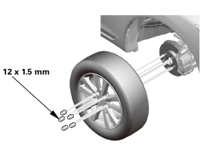 12x1mm
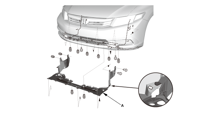
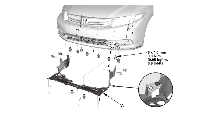
| 4. | Splash Shield |
|
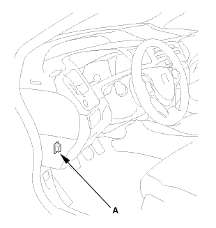
1. |
Remove the splash shield (A). |
| 5. | Radiator Cap |
|
| 6. | Radiator Coolant - Replacement |
|
|
|
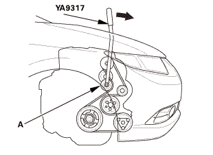
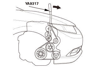
| 7. | Drive Belt |
|
|
|
 vnm
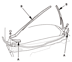
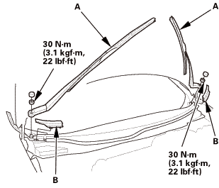
vnm| 8. | Wiper Arm Assembly |
|
|
|
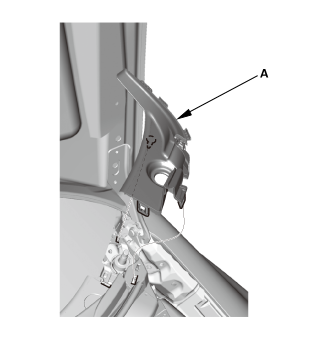
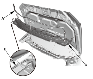
| 9. | Both Side Cowl Covers |
|
|
|
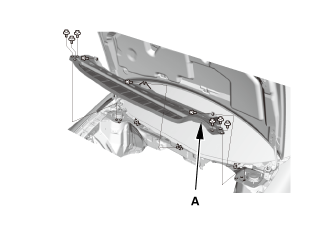
| 10. | Center Cowl Cover |
|
|
|

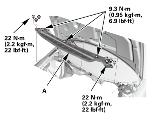
| 11. | Under Cowl Panel |
|
|
|
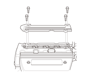
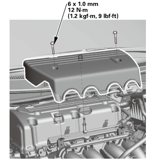
| 12. | Engine Cover |
|
|
|
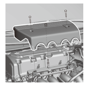
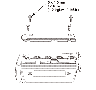
| 13. | Ignition Coil Cover |
|
|
|
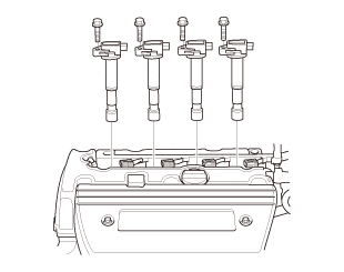
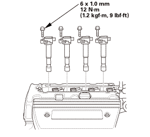
| 14. | Ignition Coil |
|
|
|
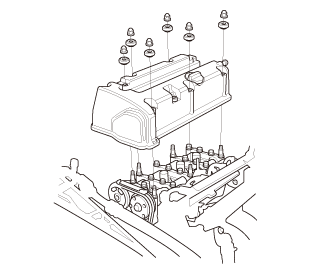
| 15. | Cylinder Head Cover |
|
|
|
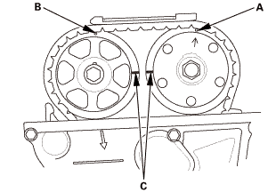
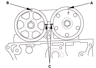
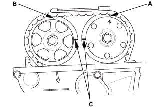
| 16. | Set The Crankshaft To Top Dead Center |
|
|
|
||||||
| 17. | Set The No.1 Piston at Top Dead Center (With Cam Chain Case/Oil Pump) |
|
|
|
| 18. | Cam Chain Case Peripheral Assembly |
|
|
|
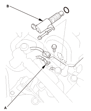
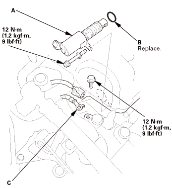
| 19. | VTC Oil Control Solenoid Valve |
|
|
|
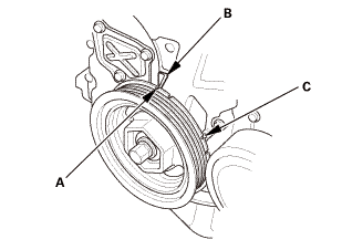
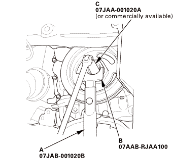
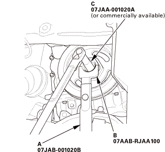
| 20. | Crankshaft Pulley |
|
|
|
 1aah(jaal0a
| 21. | Engine Jack Support (State Of A Low Vehicle) |
|
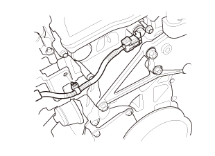
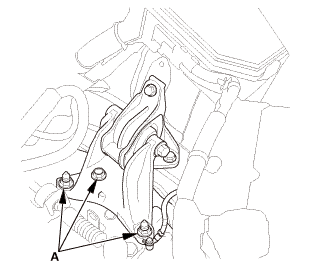
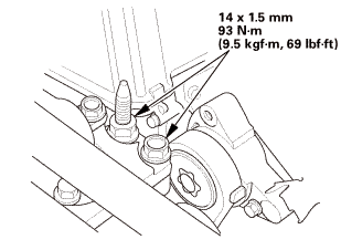
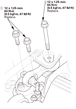
| 22. | Upper Torque Rod |
|
|
|
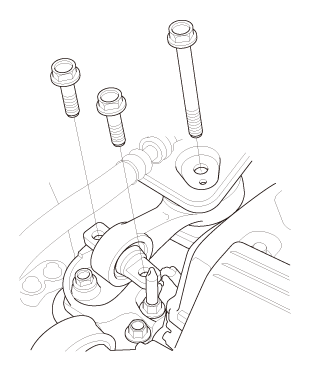
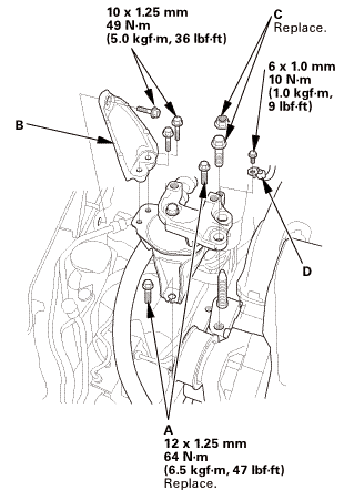
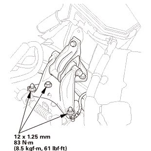
| 23. | Side Engine Mount |
|
|
|
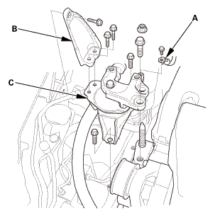
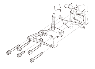
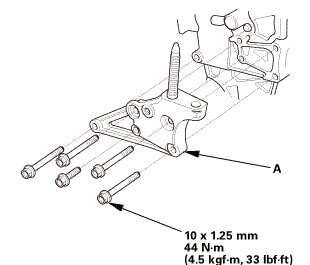
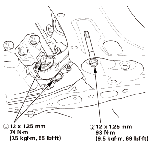
| 24. | Side Engine Mount Bracket, Engine Side |
|
|
|
| 25. | Cam Chain Case |
|
|
|
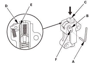
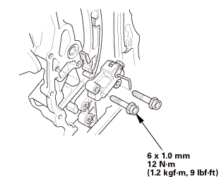
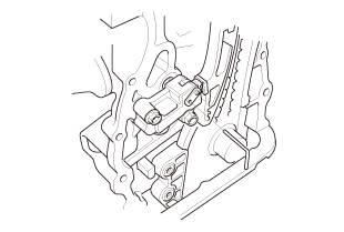
| 26. | Cam Chain Auto-Tensioner |
|
|
|
|
|
|
||||||
|
|
|
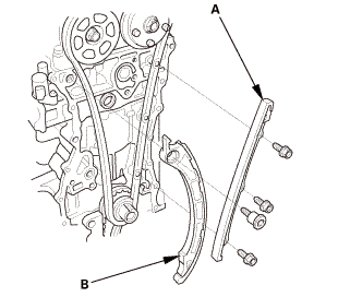
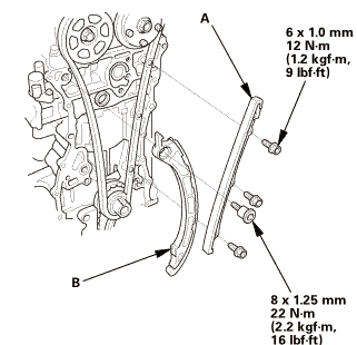
| 27. | Cam Chain Tensioner Arm and Cam Chain Guide |
|
|
|
|
|
|
| 28. | Cam Chain |
|
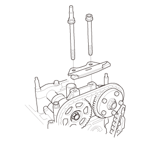
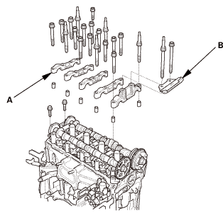
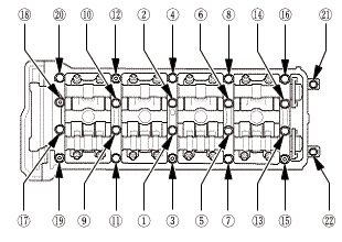
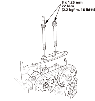
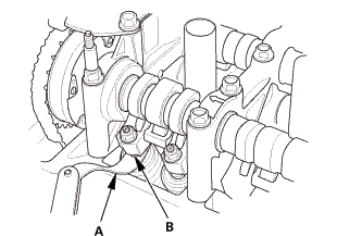
| 29. | Camshaft Holder |
|
|
|
|
|
|
|
|
|

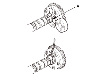
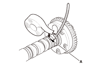
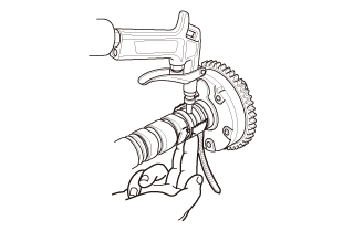
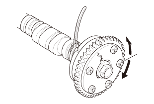
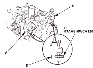
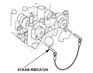
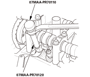
| 1. | VTC Actuator - Inspection |
|
|
|
|
|
|
|
|
|
|
|
|

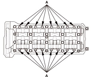
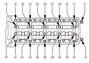
| 1. | Camshaft Holder |
|
|
|
|
|
|
||||||||||||
 ,
,

| 2. | Set The Crankshaft To Top Dead Center |
|
|
|
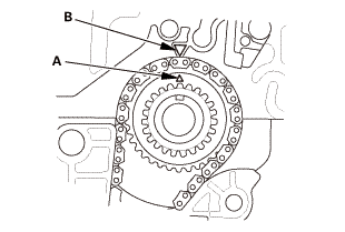
| 3. | Set The Cam Shaft To Top Dead Center (Without Cam Chain Case/Oil Pump) |
|
|
|
| 4. | Cam Chain |
|
|
|
|
|
|
|
|
|
| 5. | Cam Chain Tensioner Arm and Cam Chain Guide |
|
|
|
|
|
|
 (21m,mm
| 6. | Cam Chain Auto-Tensioner |
|
|
|
||||||
|
|
|
|
|
|
|
|
|
| 7. | Cam Chain Case |
|
|
|
|||||||||||||||||||||||||||

|
|
|
|||||||||||||||||||||
 .min)
.min)|
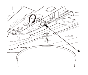
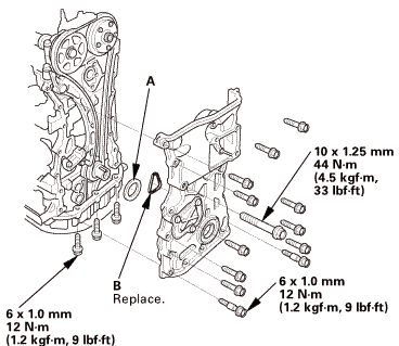
6. |
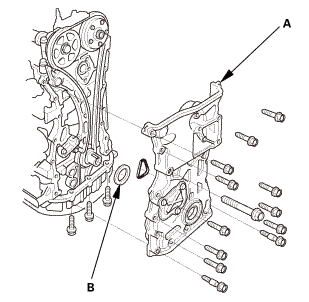
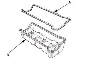
Install the spacer (A), then install a new O-ring (B) on the chain case. Set the edge of the chain case (C) to the edge of the oil pan (D), then install the chain case on the engine block (E). Wipe off the excess liquid gasket on the oil pan and the chain case mating area. |
|||||||||||||
|
NOTE: |
||||||||||||||
|
||||||||||||||
 tommi2mmu....

| 8. | Side Engine Mount Bracket, Engine Side |
|
|
|
| 9. | Side Engine Mount |
|
|
|
 replace.(s.nm,
| 10. | Transmission Mount - Loosen |
|
|
|
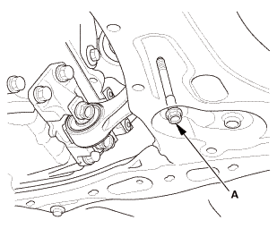
| 11. | Lower Torque Rod Mounting Bolt - Loosen |
|
|
|
| 12. | Side Engine Mount - Tighten |
|
|
|
 -.smmn-m
| 13. | Transmission Mount - Tighten |
|
|
|
 :2mmn-m
| 14. | Lower Torque Rod Mounting Bolt - Tighten |
|
|
|
| 15. | Air Cleaner Assembly |
|
|
|
| 16. | Upper Torque Rod |
|
|
|
 mmreplace.mm
| 17. | Crankshaft Pulley |
|
|
|
|
|
|
 1aah(jaal0a
| 18. | Splash Shield |
|
1. |
Install the splash shield (A). |
| 19. | VTC Oil Control Solenoid Valve |
|
|
|
||||||||||||||||||||
| 20. | Cam Chain Case Peripheral Assembly |
|
|
|
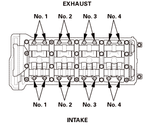
| 21. | Valve Clearance - Adjustment |
|
|
|
|
2. |
Select the correct feeler gauge for the valve clearance you are going to check. |
|||||||||
|
||||||||||
|
|
|
|
|
|
|||||||||||||||
|
|
|
|
|
|
|
|
|
| 22. | Cylinder Head Cover |
|
|
|
||||||||||||
|
|
|
||||||||||||
|
|
|
|
|
|
|||||||||||||||||
| 23. | Ignition Coil |
|
|
|
| 24. | Ignition Coil Cover |
|
|
|
| 25. | Engine Cover |
|
|
|
| 26. | Under Cowl Panel |
|
|
|
 22mm)2222
| 27. | Center Cowl Cover |
|
|
|
| 28. | Both Side Cowl Covers |
|
|
|
| 29. | Wiper Arm Assembly |
|
|
|
 1.122
1.122| 30. | Drive Belt |
|
|
|
 vnm
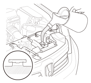
vnm| 31. | Radiator Coolant - Replacement |
|
1. |
Follow the chart and pour coolant into the radiator up to the base of the filler neck. |
|||||||||||||||||||||||||||||||||||||
|
NOTE: |
||||||||||||||||||||||||||||||||||||||
|
||||||||||||||||||||||||||||||||||||||
|
||||||||||||||||||||||||||||||||||||||
|
*: When you want to winterize the coolant with the minimum amount of coolant change but the current coolant concentration in the vehicle is unknown, you must drain all coolant from the cooling system. |
||||||||||||||||||||||||||||||||||||||
|
||||||||||||||||||||||||||||||||||||||
|
||||||||||||||||||||||||||||||||||||||
|
||||||||||||||||||||||||||||||||||||||
|
||||||||||||||||||||||||||||||||||||||
| 32. | Tire and Wheel-Installation, Front Right |
|
|
|
||||||
 mminmuan
| 33. | HDS DLC - Connection |
|
|
|
| 34. | CKP Pattern Clear/CKP Pattern Learn |
|
| 35. | Maintenance Minder Reset |
|
 Exhaust Camshaft Sprocket Removal and Installation (K24Z7)
1101U9
Removal
1.
Wiper Arm Assembly
NOTE: Set the wiper arms to the auto-stop position before removal.
...
 VTC Actuator Removal and Installation (K24Z7)
110153
Removal
1.
Wiper Arm Assembly
NOTE: Set the wiper arms to the auto-stop position before removal.
...
See also:
Honda Civic Owners Manual. Oil Check
We recommend that you check the engine oil level every time you refuel.
Park the vehicle on level ground.
Wait approximately three minutes after turning the engine off before you check
the
oil.
Remove the dipstick (orange).
Wipe the dipstick with a clean cloth or
paper towel ...
