Honda Civic Service Manual: Synchro Ring and Gear Inspection (R18Z1 M/T)

Removal
| 1. | M/T Change Lever Assembly |
|
|
|
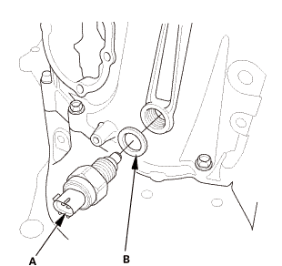
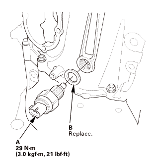
| 2. | Back Up Light Switch |
|
|
|
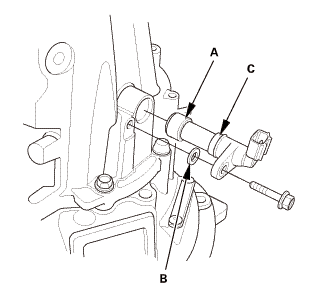
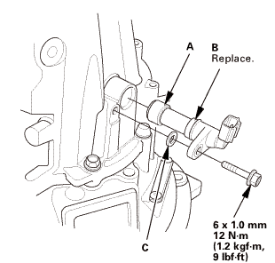
| 3. | M/T Output Shaft Speed Sensor |
|
|
|
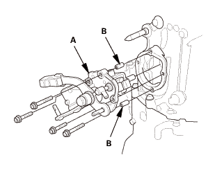
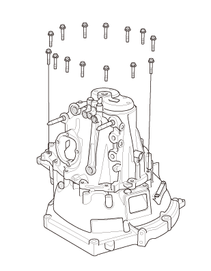
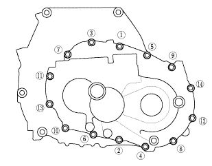
| 4. | M/T Transmission Housing Assembly |
|
|
|
|
|
|
|
|
|
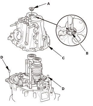
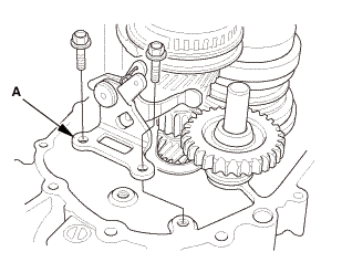
| 5. | M/T Reverse Shift Fork |
|
|
|
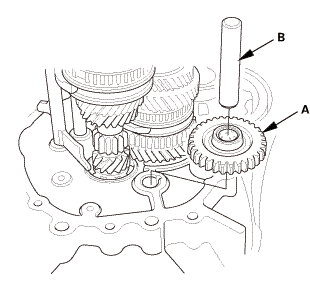
| 6. | Reverse Idler Gear |
|
|
|
| 7. | M/T Mainshaft and Countershaft and Shift Fork Assembly |
|
|
|
|||||||||||||||
| 8. | M/T Mainshaft 5th Gear |
|
|
|
|
|
|
| 9. | M/T Mainshaft 3rd and 4th Gear |
|
|
|
| 10. | M/T Countershaft |
|
|
|
|
|
|
|
|
|
|
|
|
|
|
|
 Inspection
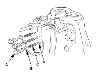
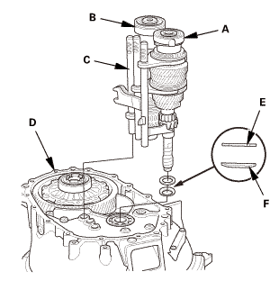
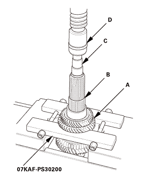
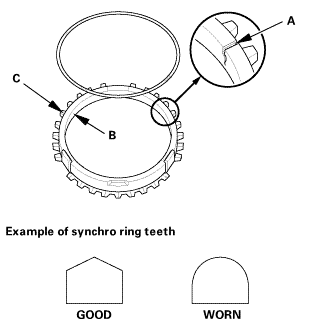
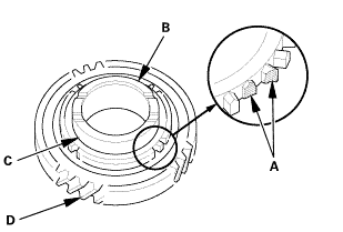
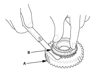
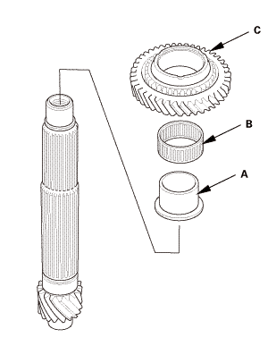
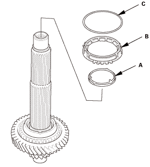
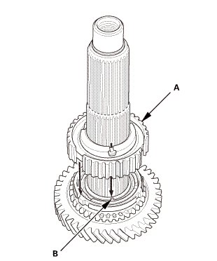
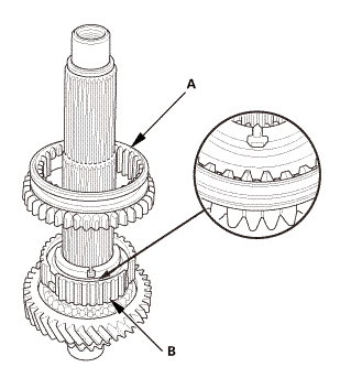
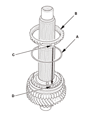
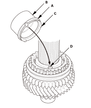
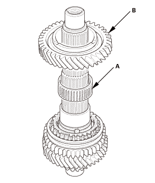
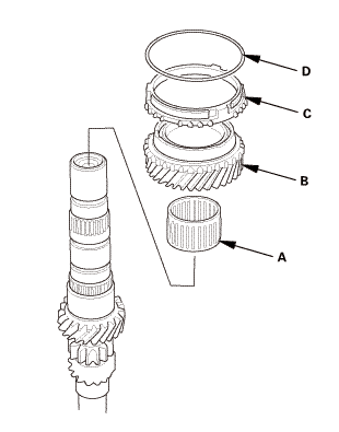
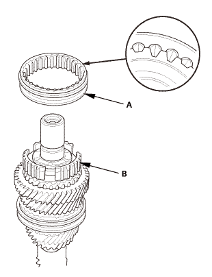
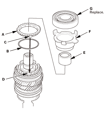
| 1. | Synchro Ring and Gear Inspection |
|
|
|
|
|
|
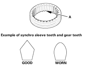 sleeveandworm
|
|
|
||||||||||||||||||
|
Synchro ring-to-gear
|
|
||||||||||||||||||


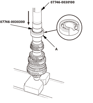
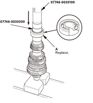
Installation
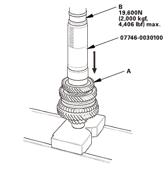
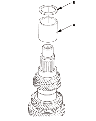
| 1. | M/T Countershaft |
|
|
|
|
|
|
|
|
|
|
|
|
||||||
|
|
|
|
|
|
|
|
|
|
|
|
||||||
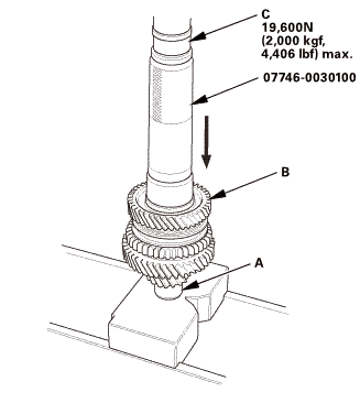 is.soonim)mix.
|
|
|
||||||
 1s,sonnx2,aaa
|
|
|
||||||
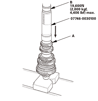 max.
max.|
|
|
|
|
|
|
|
|
||||||||||||||||||||||||||||||||||||||||||||||||||||||||||||
|
|
|
|
|
|
|||||||||||||||
|
|
|
|||||||||
| 2. | M/T Mainshaft 3rd and 4th Gear |
|
|
|
|
|
|
||||||
|
|
|
|
|
|
|
|
|
| 3. | M/T Mainshaft 5th Gear |
|
|
|
|
|
|
|
|
|
|
|
|
|||||||||
|
|
|
|
|
|
| 4. | M/T Mainshaft and Countershaft and Shift Fork Assembly |
|
|
|
||||||||||||||||||
| 5. | Reverse Idler Gear |
|
|
|
| 6. | M/T Reverse Shift Fork |
|
|
|
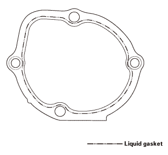
| 7. | M/T Transmission Housing Assembly |
|
|
|
||||||||||||||||||||

|
|
|
||||||||||||||||||
 imto
imto|
|
|
|||||||||||||||||||||||
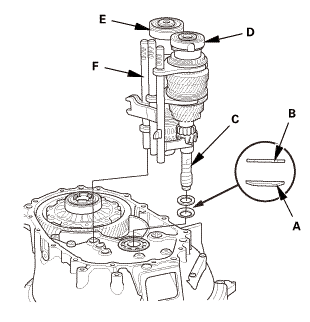
 as installed:
3.3-6.5 mm (0.130-0.256 in)
as installed:
3.3-6.5 mm (0.130-0.256 in)|
|
|
|
|
|
||||||||||
|
|
|
 2215
2215| 8. | M/T Output Shaft Speed Sensor |
|
|
|
| 9. | Back Up Light Switch |
|
|
|
| 10. | M/T Change Lever Assembly |
|
|
|
||||||||||||||||||||
 -mid
-mid|
|
|
 .omm-m(i.2kvf-m.9bm1!
 Synchro Ring and Gear Inspection (K24Z7)
Removal
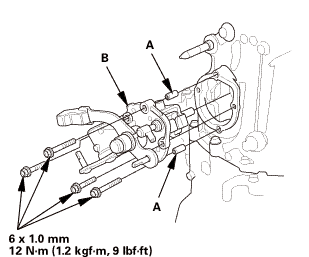
1.
M/T Change Lever Assembly
1.
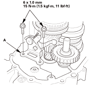
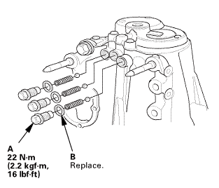
Remove the interlock bolt (A).
...
 Synchro Sleeve and Hub Disassembly, Reassembly, and Inspection (K24Z7)
Disassembly
1.
M/T Change Lever Assembly
1.
Remove the interlock bolt (A).
...
See also:
Honda Civic Owners Manual. Locking a Door Without Using a Key
Locking the driver’s door
Push the lock tab forward or
push the
master door lock switch in the lock direction
, and close the door.
Locking the passenger’s doors
Push the lock tab forward and close the door.
Lockout prevention system
Models without smart entry system
The doo ...
