|
|
|
Use commercially available computerized four wheel alignment
equipment to measure wheel alignment (caster, camber, toe, and turning
angle). Follow the equipment manufacturer's instructions.
|
|
1.
|
Turn the wheel right and left while applying the brake, and measure
the turning angle of both wheels.
|
|
USA and Canada models
|
Turning angle:
|
| |
Except Si:
|
| |
|
Inward:
|
38 ° 30 ’±2 °
|
| |
|
Outward (reference):
|
30 ° 47 ’±1 °
|
| |
Si (Without 18 inch wheel):
|
| |
|
Inward:
|
38 ° 22 ’±2 °
|
| |
|
Outward (reference):
|
30 ° 41 ’±1 °
|
| |
Si (With 18 inch wheel):
|
| |
|
Inward:
|
36 ° 33 ’±2 °
|
| |
|
Outward (reference):
|
29 ° 53 ’±1 °
|
|
|
|
|
Mexico models
|
Turning angle:
|
| |
Without 18 inch wheel:
|
| |
|
Inward:
|
39 ° 12 ’±2 °
|
| |
|
Outward (reference):
|
31 ° 14 ’±1 °
|
| |
With 18 inch wheel:
|
| |
|
Inward:
|
36 ° 58 ’±2 °
|
| |
|
Outward (reference):
|
30 ° 16 ’±1 °
|
|
|
|
|
2.
|
If the measurement is not within the specifications, even up
both sides of the tie-rod threaded section length while adjusting
the front toe.
|
|
3.
|
If it is correct, but the turning angle is not within the specifications,
check for bent or damaged suspension components.
|
|


 ov
ov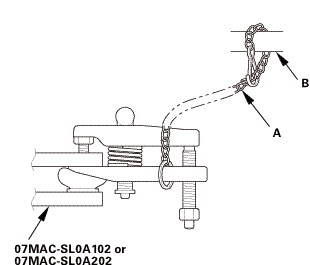 wmae-sldaidz

 o1vags2xuiuu
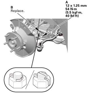 i2mmonum
 mmmln-mnomm
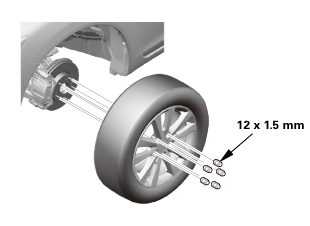
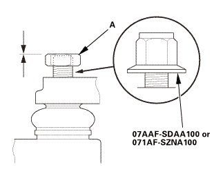
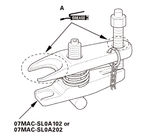
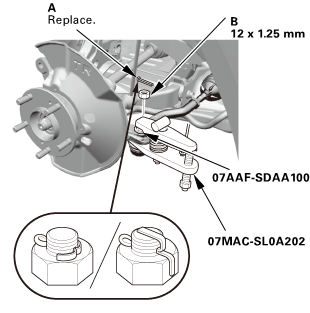
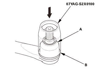
 Front Lower Ball Joint Removal and Installation
