Honda Civic Service Manual: M/T Countershaft Disassembly, Reassembly, and Inspection (K24Z7)
 Disassembly
|
NOTE: Refer to the Exploded View as needed during this procedure. |
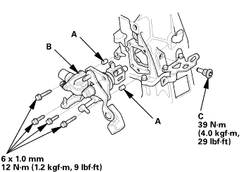
| 1. | M/T Change Lever Assembly |
|
|
|

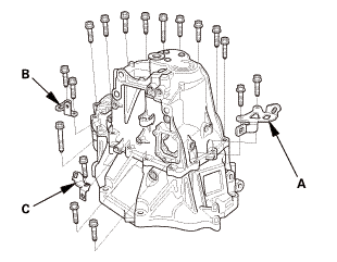
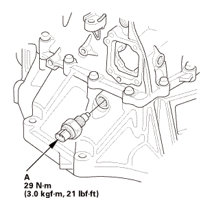
| 2. | Back-Up Light Switch |
|
|
|
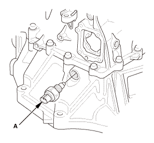
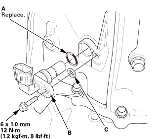
| 3. | Output Shaft (Countershaft) Speed Sensor |
|
|
|
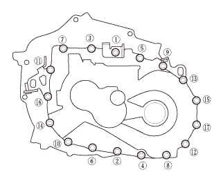
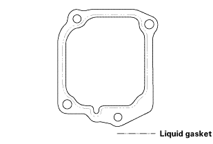
| 4. | Transmission Housing |
|
|
|
|
|
|
|
|
|
|
|
|
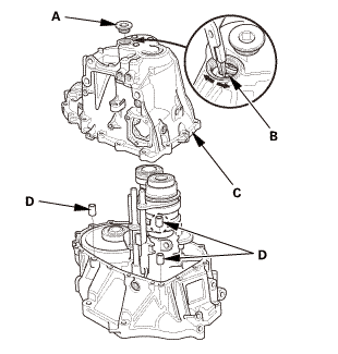
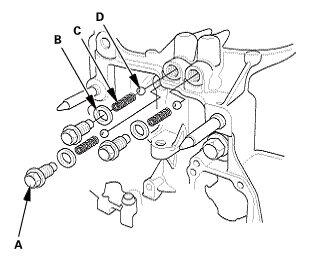
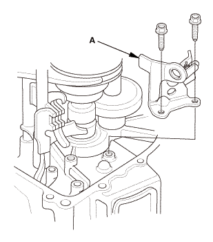
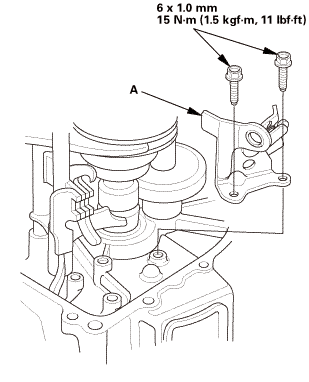
| 5. | Reverse Shift Fork |
|
|
|
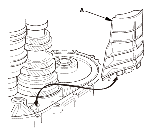
| 6. | Baffle Plate |
|
|
|
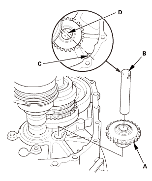
| 7. | Reverse Idler Gear |
|
|
|
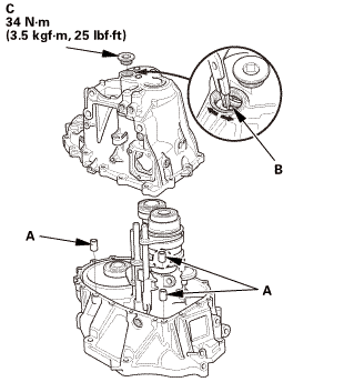
| 8. | M/T Mainshaft and Countershaft and Shift Fork Assembly |
|
|
|
|||||||||||||||
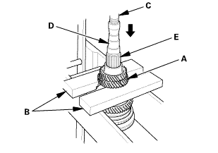
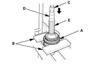
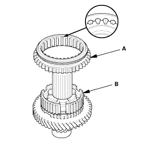
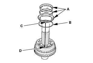
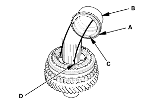
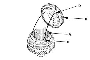
| 9. | M/T Countershaft |
|
|
|
|
|
|
|
|
|
|
|
|
 Inspection
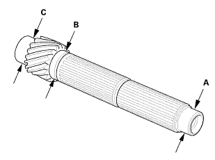
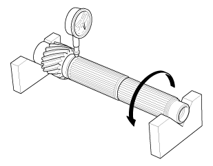
| 1. | M/T Countershaft Inspection |
|
|
|
||||||||||||||||||||||||||||||||||
|
|
|
|||||||||||||
 View
View
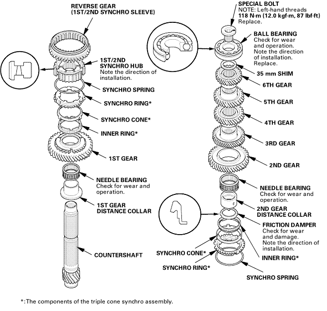
| 1. | M/T Countershaft Exploded View |
|
Exploded View |
 umuzreplaceandmsahahunmmnom:(aha(mnspringgeargearavvddamagsdwemmvat
 Reassembly
|
NOTE: Refer to the Exploded View as needed during this procedure. |
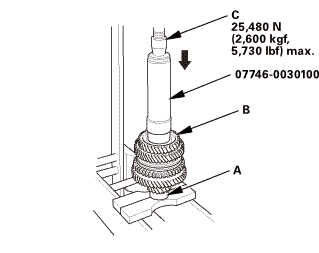
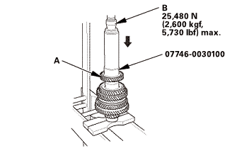
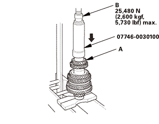
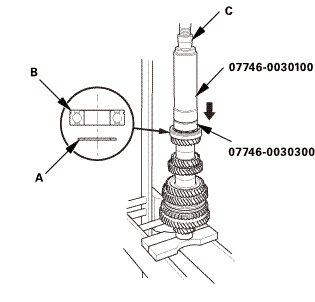
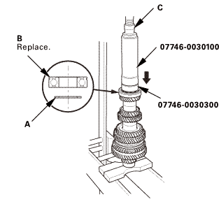
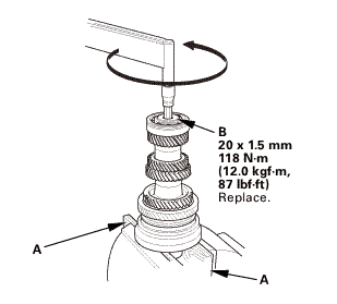
| 1. | M/T Countershaft |
|
|
|
|
|
|
|
|
|
|
|
|
|||||||||
|
|
|
|
|
|
|
|
|
|
|
|
|||||||||
 sun
sun|
|
|
||||||
 s,m
s,m|
|
|
||||||
 (2,snn
|
|
|
||||||
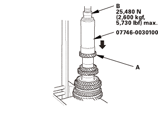 zs,4ioums.uuau1uu
|
|
|
||||||||||||||||||||
 nms.nn:mnn
|
|
|
||||||||||||||||||||||||||||||||||||||||||||||||||||||||||||||||||||||||||||||
|
|
|
|
|
|
||||||
|
|
|
|||||||||||||||
 nms.nu:n1nn
|
|
|
|||||||||
 mm(noumn
| 2. | M/T Mainshaft and Countershaft and Shift Fork Assembly |
|
|
|
||||||||||||||||||

| 3. | Reverse Idler Gear |
|
|
|
| 4. | Baffle Plate |
|
|
|
| 5. | Reverse Shift Fork |
|
|
|
 mmlbf!
| 6. | Transmission Housing |
|
|
|
||||||||||||||||||||

|
|
|
|||||||||||||||
|
|
|
|||||||||||||||||||||||
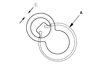
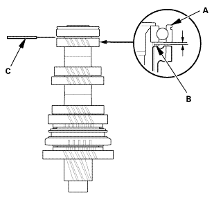
 as installed:
3.3-6.0 mm (0.130-0.236 in)
as installed:
3.3-6.0 mm (0.130-0.236 in)|
|
|
|
|
|
||||||||||
|
|
|
|
|
|
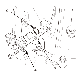
| 7. | Output Shaft (Countershaft) Speed Sensor |
|
|
|
| 8. | Back-Up Light Switch |
|
|
|
| 9. | M/T Change Lever Assembly |
|
|
|
||||||||||||||||||||
 iukn
iukn|
|
|
 M/T Countershaft Bearing Replacement (R18Z1 M/T)
Removal
1.
M/T Change Lever Assembly
1.
Remove the change lever assembly (A).
...
 M/T Mainshaft Assembly Clearance Inspection (K24Z7)
Removal
1.
M/T Change Lever Assembly
1.
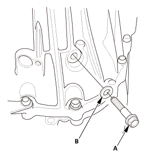
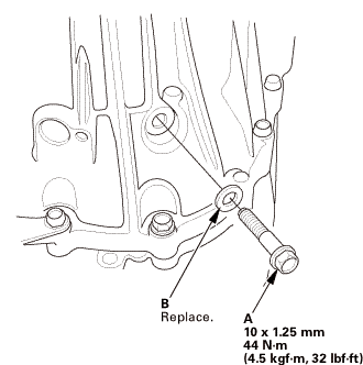
Remove the interlock bolt (A).
...
See also:
Honda Civic Service Manual. License Plate Light Removal and Installation - Double Lights ('13-'14: 4-door)
1.
Trunk Lid Trim Panel
1.
Remove the trunk lid trim panel (A).
2.
Inner Taillight Both
1.
Disconnect ...
