Honda Civic Service Manual: Valve Guide Replacement (R18Z1)

| 1. | Vehicle Lift |
|
| 2. | Tire and Wheel-Removal, Front Right |
|
|
|
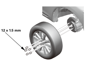 12x1mm
| 3. | Fuel Filler Cap |
|
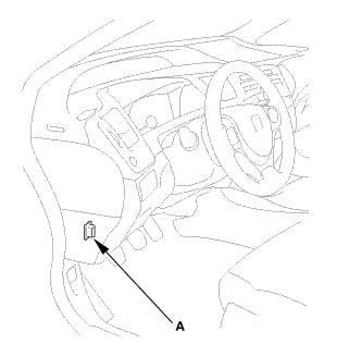
| 4. | HDS DLC - Connection |
|
|
|
| 5. | Fuel Pump Off |
|
||||||||||||||||||||||||

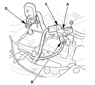
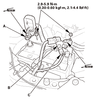
| 6. | Battery Terminal - Disconnection |
|
|
|
|||||||||||||||||||||||||||
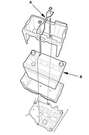
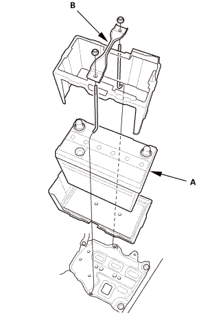
| 7. | Battery |
|
|
|
| 8. | Fuel Pressure - Relieving |
|
|
|
|
|
|
|
|
|
|||||||||||||||||||||||||
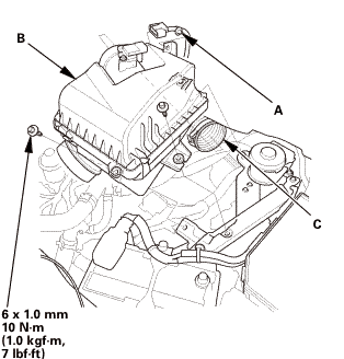
| 9. | Engine Cover |
|
|
|
| 10. | Radiator Cap |
|
| 11. | Radiator Coolant - Replacement |
|
|
|
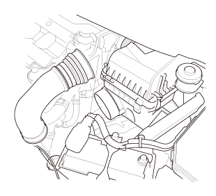
| 12. | Intake Air Pipe |
|
|
|
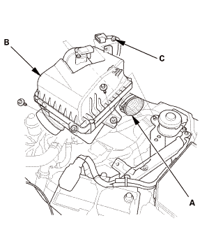
| 13. | Air Cleaner |
|
|
|
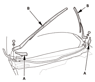
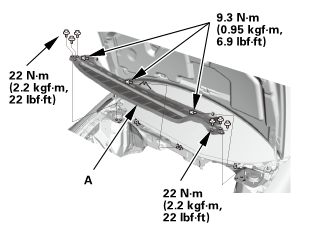
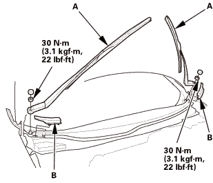
| 14. | Wiper Arm Assembly |
|
|
|
| 15. | Both Side Cowl Covers |
|
|
|
| 16. | Center Cowl Cover |
|
|
|

| 17. | Under Cowl Panel |
|
|
|
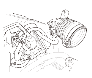
| 18. | Intake Air Duct |
|
|
|
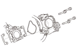
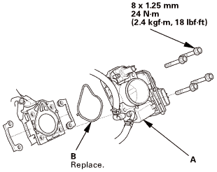
| 19. | Throttle Body - Removal |
|
|
|
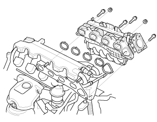
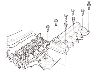
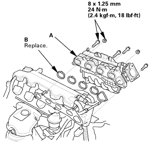
| 20. | Intake Manifold Assembly |
|
|
|
|
|
|
|
|
|
|
|
|
|
|
|
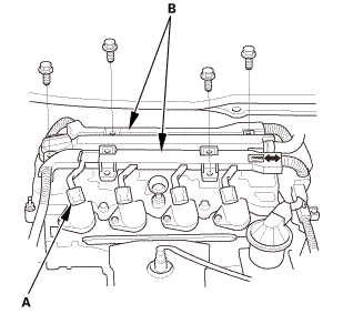
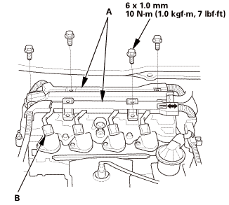
| 21. | Cylinder Head Peripheral Assembly |
|
|
|
|
|
|
|
|
|
|
|
|
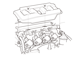
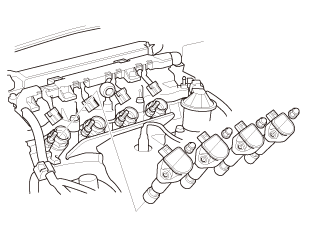
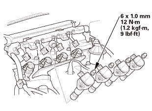
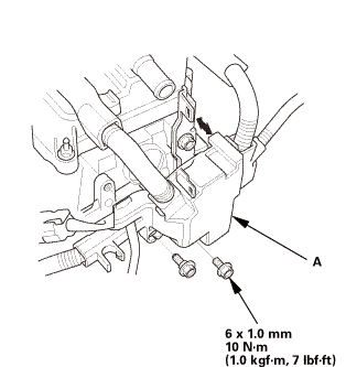
| 22. | Ignition Coil |
|
|
|
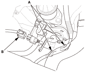
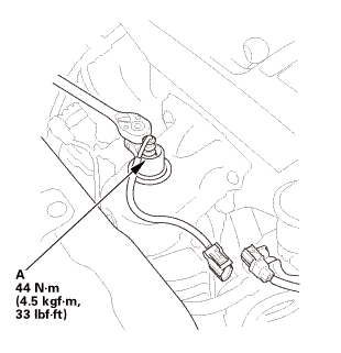
| 23. | A/F Sensor (Sensor 1) |
|
|
|
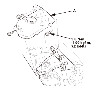
| 24. | Exhaust Chamber Cover |
|
|
|
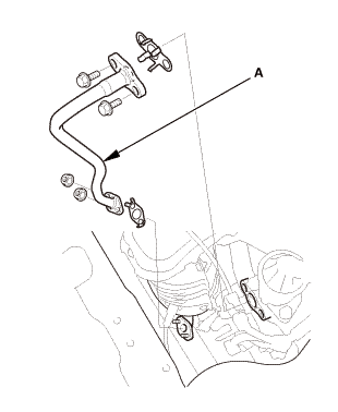
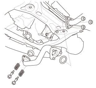
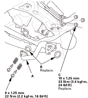
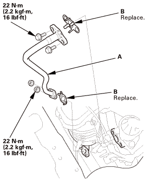
| 25. | EGR Pipe |
|
|
|
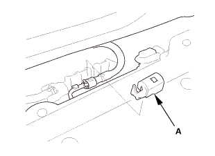
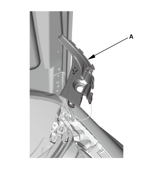
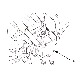
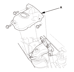
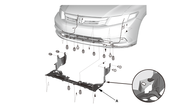
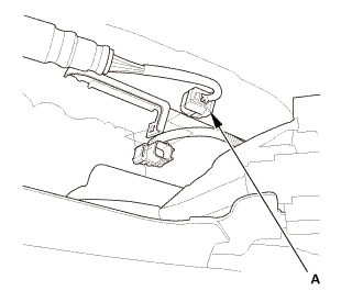
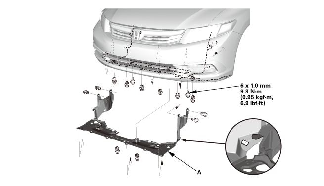
| 26. | Splash Shield |
|
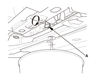
1. |
Remove the splash shield (A). |
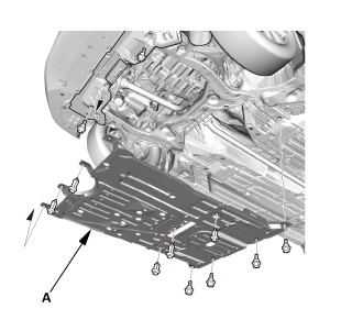
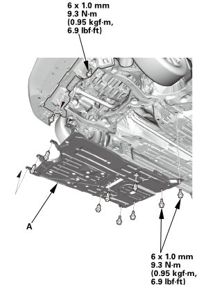
| 27. | Engine Undercover |
|
|
|
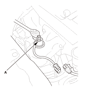
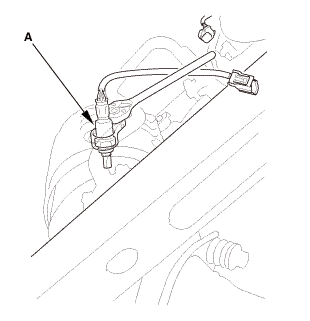
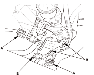
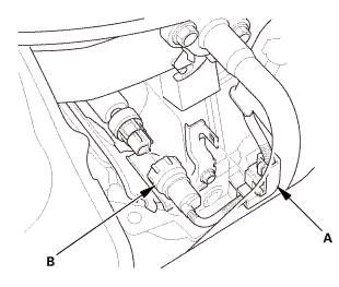
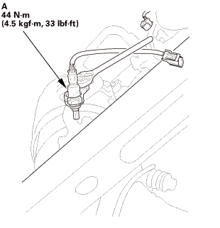
| 28. | Secondary HO2S |
|
|
|
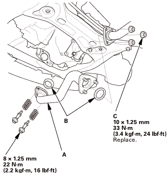
| 29. | Exhaust Pipe A (Except CVT) |
|
|
|
| 30. | Exhaust Pipe A (CVT) |
|
|
|
|
|
|
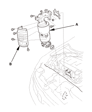
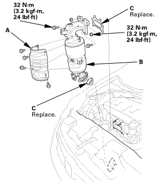
| 31. | Catalytic Converter |
|
|
|
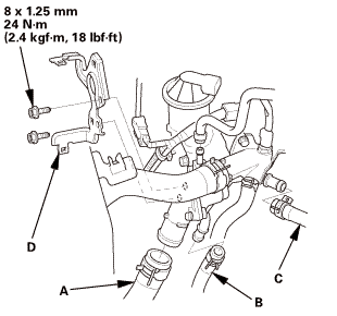
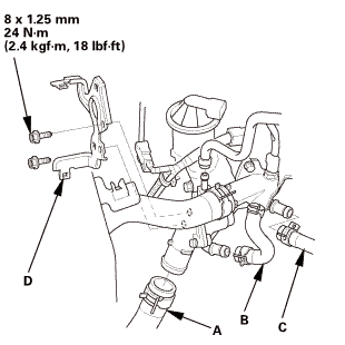
| 32. | Thermostat Housing Peripheral Assembly |
|
Except CVT
CVT
|
|
|
|
|
|
Except M/T
M/T
|
|
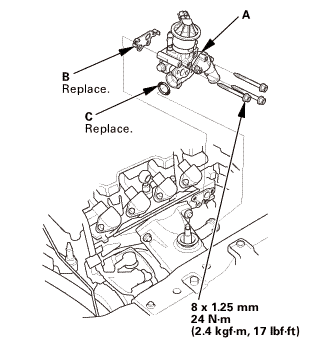
| 33. | Thermostat Housing |
|
|
|
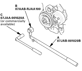
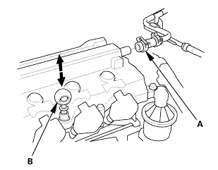
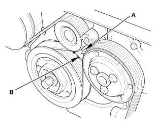
| 34. | Water Pump Pulley Mounting Bolt - Loosen |
|
|
|
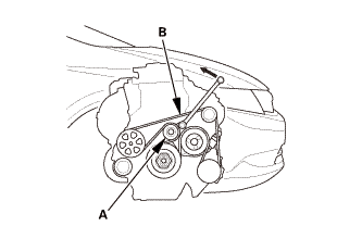
| 35. | Drive Belt |
|
|
|
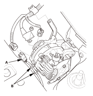
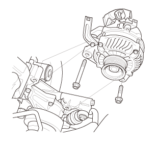
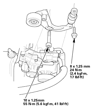
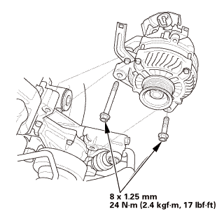
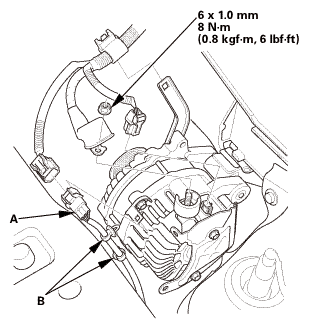
| 36. | Alternator |
|
|
|
|
|
|
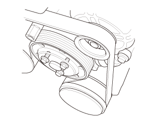
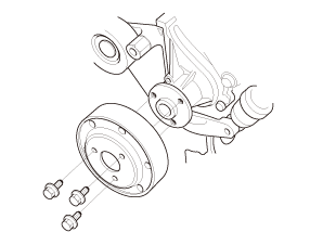
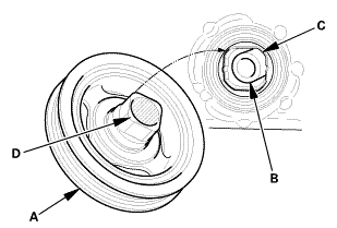
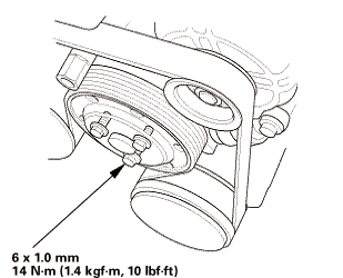
| 37. | Water Pump Pulley |
|
|
|
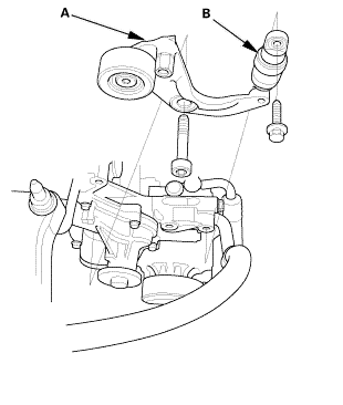
| 38. | Auto Tensioner Assembly |
|
|
|
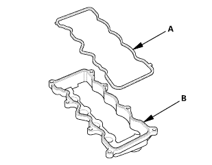
| 39. | Cylinder Head Cover and/or Packing |
|
|
|
|
|
|
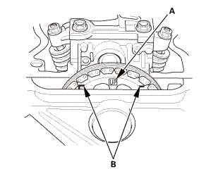
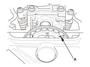
| 40. | Check The No.1 Piston at Top Dead Center (With Cam Chain Case/Oil Pump) |
|
|
|
| 41. | Crankshaft Pulley |
|
|
|
 [av
[av| 42. | Engine Jack Support (State Of A Low Vehicle) |
|
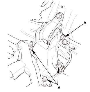
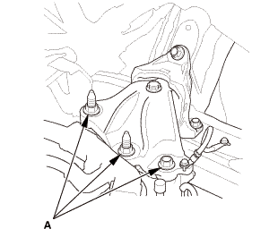
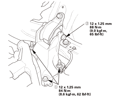
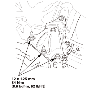
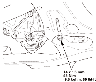
| 43. | Mounting Bracket, Engine Side |
|
|
|
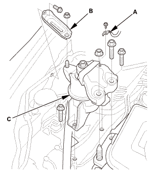
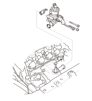
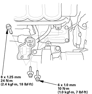
| 44. | Engine Oil Pump Assembly |
|
|
|
|
|
|
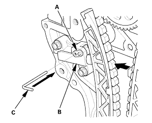
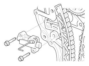
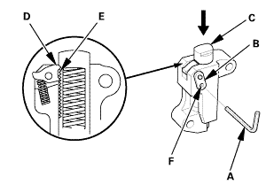
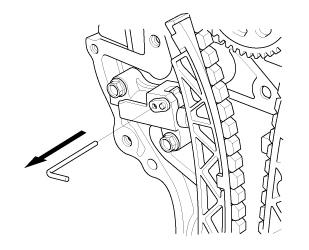
| 45. | Cam Chain Auto-Tensioner |
|
|
|
||||||||||||
|
|
|
|
|
|
||||||||||||
|
|
|
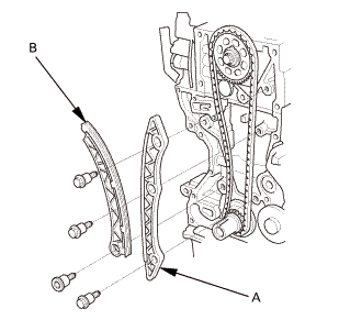
| 46. | Cam Chain |
|
|
|
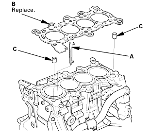
| 47. | Cylinder Head Assembly |
|
|
|
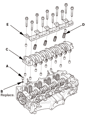
| 48. | Rocker Arm Assembly |
|
|
|
|
|
|
|
|
|
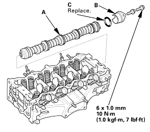
| 49. | Camshaft Sprocket |
|
|
|
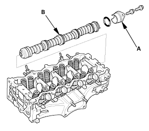
| 50. | Camshaft |
|
|
|
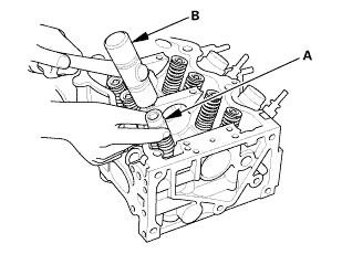
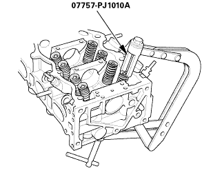
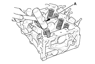
| 51. | Valve Spring |
|
|
|
|
|
|
 o77s7n
| 52. | Valve Seal |
|
|
|
|
|
|
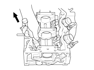
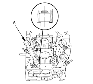
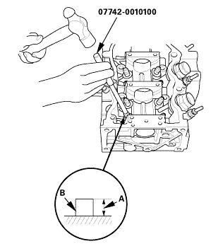
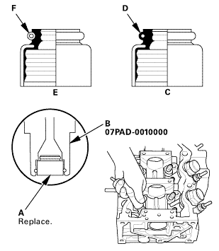
| 53. | Valve Guide |
|
|
|
 mmmmmlmmam
|
|
|
|
|
|
||||||||||||
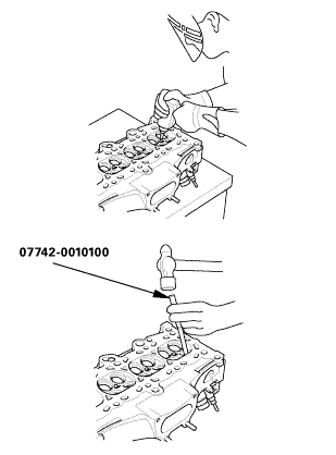

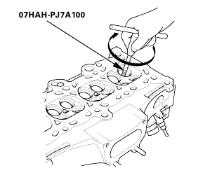
| 1. | Valve Guide |
|
|
|
||||||||||||||||
|
|
|
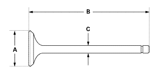
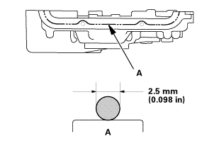
| 2. | Valve Inspection |
|
1. |
Measure the valve in these areas. |
|||||||||||||
|
||||||||||||||
|
||||||||||||||
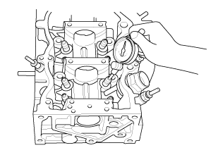
| 3. | Valve Stem To Guide Clearance Inspection |
|
1. |
Subtract the O.D. of the valve stem, measured with a micrometer, from the I.D. of the valve guide measured with an inside micrometer or a ball gauge. Take the measurements in three places along the valve stem and three places inside the valve guide. The difference between the largest guide measurement and the smallest stem measurement should not exceed the service limit. |
|||||||||||||||
|
||||||||||||||||
| 4. | Valve Seat - Inspection |
|
| 5. | Valve Seal |
|
|
|
||||||
| 6. | Valve Spring |
|
|
|
|
|
|
||||||
| 7. | Camshaft |
|
|
|
 tommnomm
| 8. | Camshaft Sprocket |
|
|
|
||||||||||||||||||||||
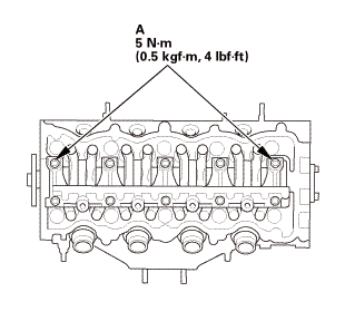
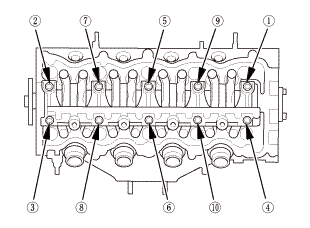
| 9. | Rocker Arm Assembly |
|
|
|
|||||||||||||||
|
|
|
|
|
|
||||||||||
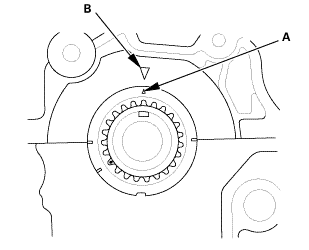
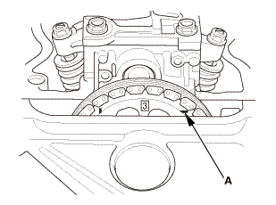
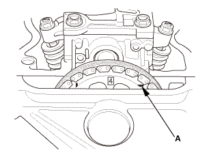
| 10. | Set The Crankshaft To Top Dead Center |
|
|
|
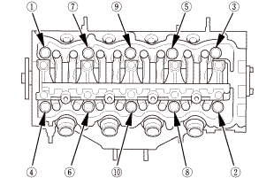
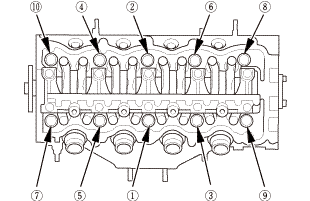
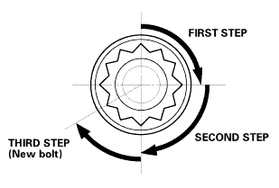
| 11. | Cylinder Head Assembly |
|
|
|
|
|
|
 inmmam
|
|
|
|
|
|
||||||
 secounstep
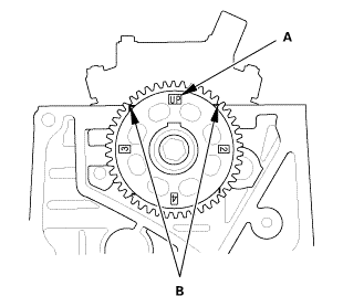
| 12. | Set The No.1 Piston at Top Dead Center (Without Cam Chain Case/Oil Pump) |
|
|
|
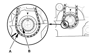
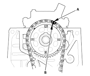
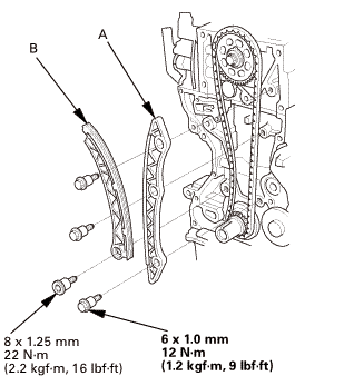
| 13. | Cam Chain |
|
|
|
|
|
|
|
|
|
 ...,is(1.2
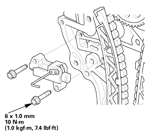
| 14. | Cam Chain Auto-Tensioner |
|
|
|
||||||
|
|
|
 nokvf-in.
|
|
|
| 15. | Engine Oil Pump Assembly |
|
|
|
||||||||||||||||||||||||||
|
|
|
||||||||||||||
|
|
|
||||||||||||||||||||||||||||||
 25mm(7(32k1n1omm12
| 16. | Mounting Bracket, Engine Side |
|
|
|
 125mmnminm.:125mm
| 17. | Engine Jack Support (State Of A Low Vehicle) |
|
| 18. | Transmission Mount Bracket Mounting Bolt - Loosen |
|
M/T
A/T
|
|
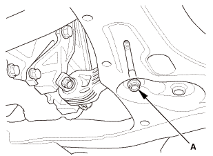
| 19. | Lower Torque Rod - Loosen |
|
|
|
| 20. | Side Engine Mount - Tighten |
|
|
|
 nxl.mm
| 21. | Transmission Mount Bracket Mounting Bolt - Tighten |
|
1. |
Tighten the transmission mount bracket mounting bolt and nuts. |
M/T
 i2mm
i2mm
A/T
 nz
nz
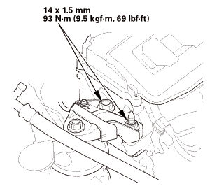
| 22. | Lower Torque Rod Mounting Bolt - Tighten |
|
|
|
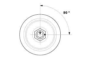
| 23. | Crankshaft Pulley |
|
|
|
|
|
|
|
|
|
|||||||||||||
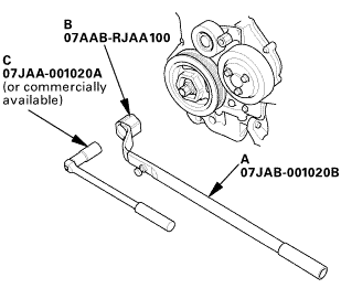 o7jaanmo2oa
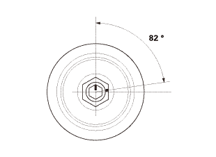
|
|
|
||||||||||
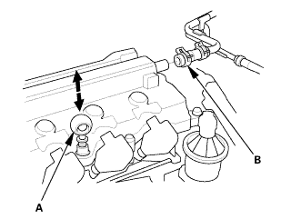
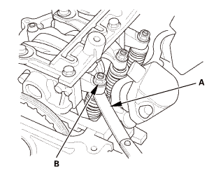
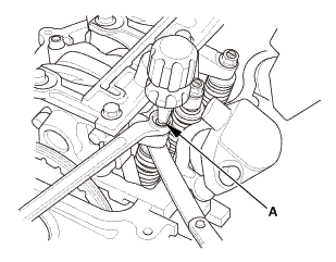
| 24. | Valve Clearance Adjustment |
|
|
|

|
2. |
Select the correct feeler gauge for the valve clearance you are going to check. |
|||||||||
|
||||||||||
 no!
no!
|
|
|
|
|
|
|||||||||||||||
|
|
|
|
|
|
|
|
|
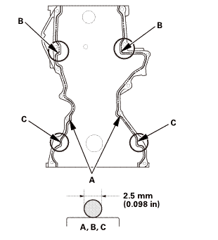
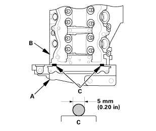
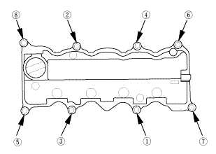
| 25. | Cylinder Head Cover and/or Packing |
|
|
|
|||||||||||||||
|
|
|
||||||||||||||||||||
|
|
|
||||||||||||||||||||
|
|
|
| 26. | Auto Tensioner Assembly |
|
|
|
 inl.25mmssn-m
| 27. | Water Pump Pulley |
|
|
|
| 28. | Alternator |
|
|
|
 mmn-m(2
|
|
|
 i.nmm(n.i
| 29. | Drive Belt |
|
|
|
| 30. | Water Pump Pulley Mounting Bolt - Tighten |
|
|
|
| 31. | Thermostat Housing |
|
|
|
 11
11| 32. | Thermostat Housing Peripheral Assembly |
|
Except M/T
M/T
|
|
|
|
|
|
Except CVT
CVT
|
|

| 33. | Catalytic Converter |
|
|
|
| 34. | Exhaust Pipe A (CVT) |
|
|
|
|
|
|
| 35. | Exhaust Pipe A (Except CVT) |
|
|
|
 inmm125mm22i21
| 36. | Secondary HO2S |
|
|
|
| 37. | Engine Undercover |
|
|
|
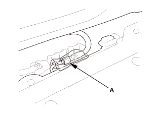
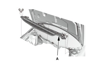
| 38. | Splash Shield |
|
1. |
Install the splash shield (A). |
| 39. | EGR Pipe |
|
|
|
 22mmmmreplace
| 40. | Exhaust Chamber Cover |
|
|
|
| 41. | A/F Sensor (Sensor 1) |
|
|
|
| 42. | Ignition Coil |
|
|
|
| 43. | Cylinder Head Peripheral Assembly |
|
|
|
|
|
|
|
|
|
|
|
|
| 44. | Intake Manifold Assembly |
|
|
|
 mm
mm|
|
|
|
|
|
|
|
|

|
|
|
| 45. | Throttle Body - Installation |
|
|
|
 mm
mm| 46. | Intake Air Duct |
|
|
|
| 47. | Under Cowl Panel |
|
|
|
 22mm)2222
| 48. | Center Cowl Cover |
|
|
|
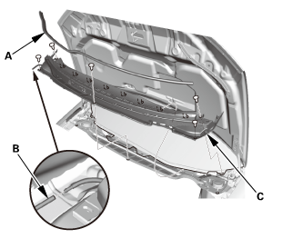
| 49. | Both Side Cowl Covers |
|
|
|
| 50. | Wiper Arm Assembly |
|
|
|
 1.122
1.122| 51. | Air Cleaner |
|
|
|
| 52. | Intake Air Pipe |
|
|
|
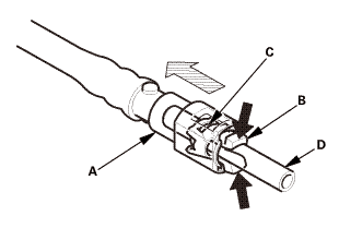
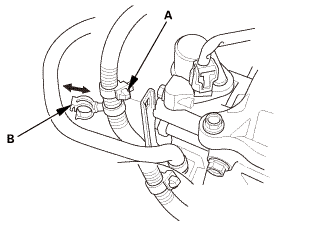
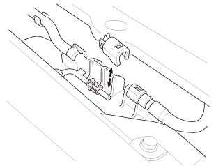
| 53. | Injector Base Fuel Feed Hose - Reconnection |
|
|
|
| 54. | Engine Cover |
|
|
|
| 55. | Battery |
|
|
|
||||||
| 56. | Battery Terminal - Reconnection |
|
|
|
|||||||||||||||||||
| 57. | HDS DLC - Connection |
|
|
|

| 58. | Fuel Pump On |
|
||||||||||
| 59. | Fuel Filler Cap |
|
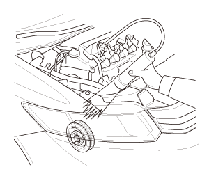
| 60. | Fuel Line Leak Check |
|
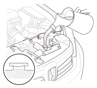
| 61. | Radiator Coolant - Replacement |
|
1. |
Follow the chart and pour coolant into the radiator up to the base of the filler neck. |
|||||||||||||||||||||||||||||||||||||
|
NOTE: |
||||||||||||||||||||||||||||||||||||||
|
||||||||||||||||||||||||||||||||||||||
|
||||||||||||||||||||||||||||||||||||||
|
*: When you want to winterize the coolant with the minimum amount of coolant change but the current coolant concentration in the vehicle is unknown, you must drain all coolant from the cooling system. |
||||||||||||||||||||||||||||||||||||||
|
||||||||||||||||||||||||||||||||||||||
|
||||||||||||||||||||||||||||||||||||||
|
||||||||||||||||||||||||||||||||||||||
|
||||||||||||||||||||||||||||||||||||||
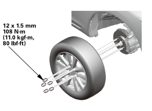
| 62. | Tire and Wheel-Installation, Front Right |
|
|
|
||||||
 mminmuan
| 63. | Warm Up The Engine |
|
| 64. | Idle Speed - Inspection |
|
||||||||||||||||||||||||||||
| 65. | CKP Pattern Clear/CKP Pattern Learn |
|
| 66. | Ignition Timing - Inspection |
|
|
|
|
|
|
||||||||||||||||
| 67. | Maintenance Minder Reset |
|
 Valve Guide Replacement (R18A9)
1.
Fuel Pressure - Relieving (Between the engine and the manual shut-off
valve) (Natural Gas Model)
Compressed natural gas is flammable and ...
 Camshaft Inspection (R18Z1)
1.
Vehicle Lift
1.
Raise the vehicle on a lift, and make sure it is securely supported.
2. ...
See also:
Honda Civic Owners Manual. Opening/Closing Windows with Auto-Open/Close Function
Automatic operation
To open: Push the switch down firmly.
To close: Pull the switch up firmly.
The window opens or closes completely. To
stop the window at any time, push or pull the
switch briefly.
Manual operation
To open: Push the switch down lightly, and
hold it until the desired ...
