Honda Civic Service Manual: Steering Column Removal and Installation

|
SRS components are located in this area. Review the SRS component locations,
and the precautions and procedures before doing repairs or service.
|
| 1. |
Battery Terminal (SRS) - Disconnection |
|
|
|
1.
|
Make sure the ignition switch is in LOCK (0).
|
|
2.
|
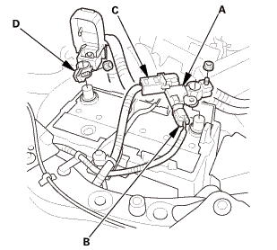
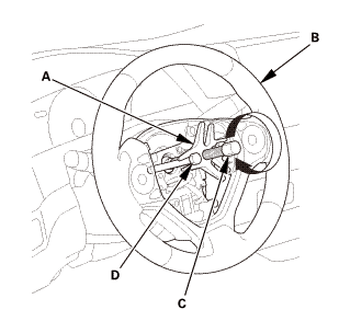
Disconnect and isolate the negative cable with the battery sensor
(A) from the battery.
|
|
NOTE:
|
|

|
Always disconnect the negative side first.
|
|
|
|
To protect the battery sensor connector (B) from
damage, do not hold it when removing the negative
terminal.
|
|
|
|
Do not disconnect the battery sensor from the
negative terminal (C).
|
|
|
|
3.
|
Disconnect the positive cable (D) from the battery.
|
|
4.
|
Wait at least 3 minutes before starting work.
|
|
|
|
|
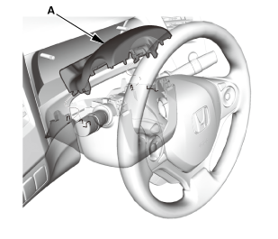
1.
|
Remove the access panel (A).
|
|
2.
|
Disconnect the driver's airbag inflator connector (B) on the
cable reel harness.
|
|
3.
|
Disconnect the horn switch connector (C).
|
|
|
|
|
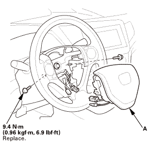
4.
|
Remove the TORX bolts using a TORX T30 bit.
|
|
5.
|
Remove the driver's airbag (A).
|
|
| 3. |
Steering Wheel Assembly |
|
 wxusmm wxusmm
|
|
1.
|
Set the front wheels in the straight ahead position.
|
|
2.
|
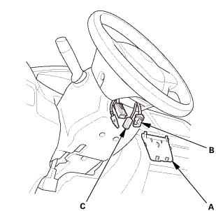
Disconnect the connector (A).
|
|
3.
|
Loosen the steering wheel bolt (B) three turns.
|
|
|
|
|
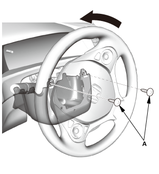
4.
|
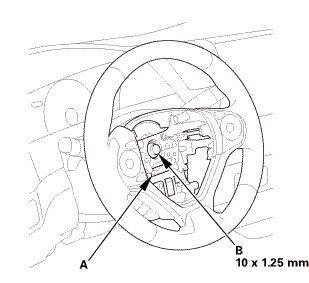
Install a commercially available steering wheel puller (A) on
the steering wheel (B).
|
|
5.
|
Free the steering wheel from the steering column shaft by turning
the pressure bolt (C) of the puller.
|
|
Note these items when removing the steering wheel:
|
|
|
Do not tap on the steering wheel or the steering
column shaft when removing the steering wheel.
|
|
|
|
If you thread the puller bolts (D) into the wheel
hub more than five threads, the bolts will hit the
cable reel and damage it. To prevent this, install
a pair of jam nuts five threads up on each puller
bolt.
|
|
|
|
|
|
|
6.
|
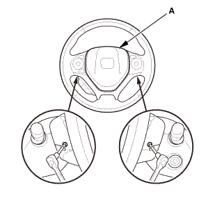
Remove the steering wheel puller.
|
|
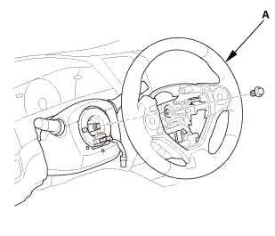
7.
|
Remove the steering wheel (A) from the steering column.
|
|
|
|
|
1.
|
Remove the upper column cover (A).
|
|
|
|
|
1.
|
Remove the screws (A).
|
|
|
|
|
2.
|
Remove the lower column cover (A).
|
|
| 6. |
Combination Switch Body Assembly |
|
|
|
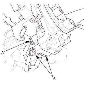
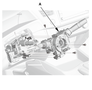
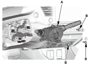
1.
|
Disconnect the connectors (A).
|
|
|
|
|
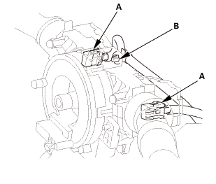
3.
|
Disconnect the connectors (A).
|
|
|
Without steering lock
With steering lock
|
|
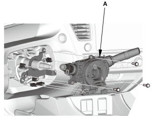
4.
|
Remove the combination switch body assembly (A) from the steering
column shaft.
|
|
|
|
|
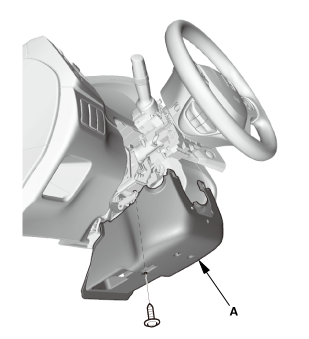
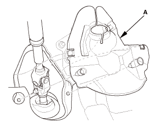
1.
|
Remove the steering joint cover (A).
|
|
| 8. |
Steering Column Lower Slide Shaft - Hold |
|
|
|
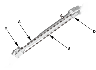
1.
|
Set the steering column to the center tilt position, and to the
center telescopic position.
|
|
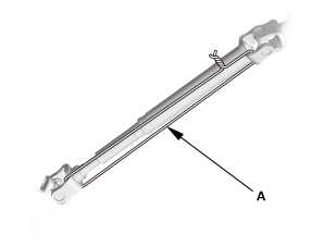
2.
|
Hold the lower slide shaft (A) on the column with a piece of
wire (B) between the joint yoke (C) of the lower slide shaft and
the joint yoke (D) of the upper shaft to prevent the lower slider
shaft from pulling out.
|
|
| 9. |
Steering Joint Bolt - Loosen |
|
|
|
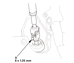
1.
|
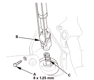
Loosen the steering joint bolt (A).
|
|
| 10. |
Steering Joint - Disconnection |
|
|
|
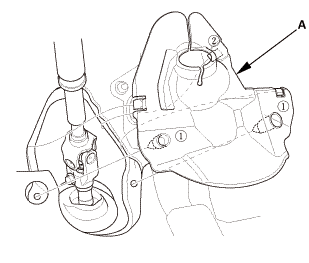
1.
|
Remove the steering joint bolt (A).
|
|
2.
|
Disconnect the steering joint (B) from the pinion shaft.
|
|
NOTE:
|
|
|
If the center guide (C) is in place and has not
moved, leave it in place.
|
|
|
|
If the center guide has come off, discard it.
|
|
|
|
|
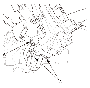
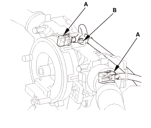
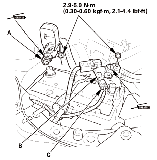
1.
|
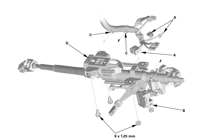
With steering lock: Disconnect the connectors (A) from the ignition switch
(B).
|
Without steering lock
With steering lock
|
2.
|
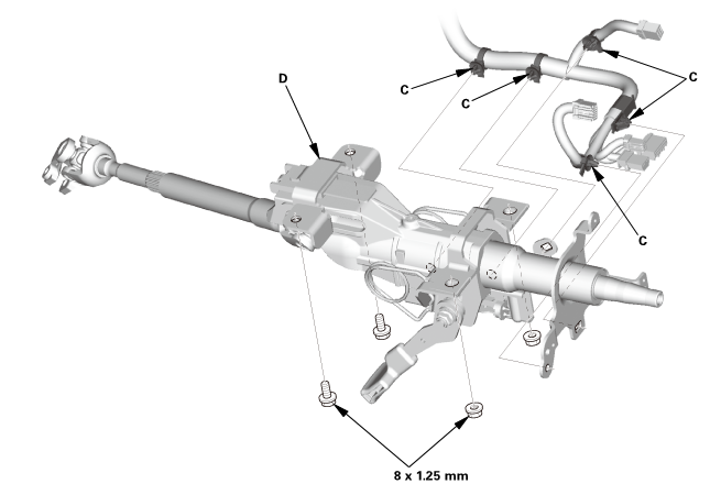
Detach the wire harness clips (C) from the steering column.
|
|
3.
|
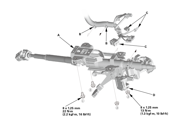
Remove the steering column (D).
|
|
NOTE: Do not release the lock lever until the steering column is installed.
If the lock lever is released before installation, adjust the steering column
after installation.
|

|
SRS components are located in this area. Review the SRS component locations,
and the precautions and procedures before doing repairs or service.
|
|
1.
|
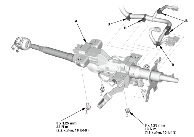
Install the steering column (A).
|
|
NOTE: Do not release the lock lever until the steering column is installed.
If the lock lever is released before installation, adjust the steering column
after installation.
|
Without steering lock
 22(22mm)
With steering lock
 u.
u.
|
2.
|
Loosely tighten the attaching nuts and bolts.
|
|
3.
|
Tighten the attaching nuts and bolts to the specified torque in the sequence
shown.
|
|
4.
|
Install the wire harness clips (B) to the steering column.
|
|
5.
|
With steering lock: Connect the connectors (C) to the ignition switch
(D).
|
| 2. |
Steering Column Lower Slide Shaft - Release |
| 3. |
Steering Joint - Reconnection |
|
|
|
1.
|
Set the rack in the straight ahead driving position.
|
|
2.
|
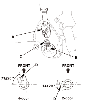
Slip the lower end of the steering joint (A) onto the pinion
shaft (B).
|
|
NOTE:
|
|
|
Pinion shaft with center guide: Install the steering
joint by aligning the center guide (C).
|
|
|
|
Pinion shaft without center guide: Position the
steering column by aligning the gap (D) within the
angle.
|
|
|
|
|
|
|
3.
|
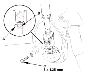
Align the bolt hole (A) on the steering joint with the groove
(B) around the pinion shaft.
|
|
4.
|
Loosely install the steering joint bolt (C).
|
|
5.
|
Be sure that the joint bolt is securely in the groove in the
pinion shaft.
|
|
6.
|
Pull on the steering joint to make sure that the steering joint
is fully seated.
|
|
| 4. |
Steering Joint Bolt - Tighten |
|
 mm:.o21 mm:.o21
|
|
1.
|
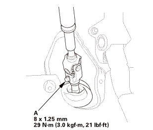
Tighten the steering joint bolt (A) to the specified torque.
|
|
|
|
|
1.
|
Install the steering joint cover (A) in the sequence shown.
|
|
| 6. |
Combination Switch Body Assembly |
|
Without steering lock
With steering lock
|
|
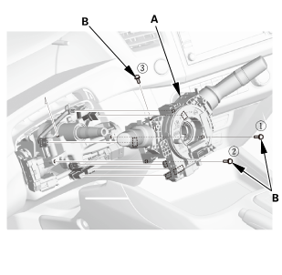
1.
|
Install the combination switch body assembly (A).
|
|
2.
|
Tighten three screws (B) in the sequence shown.
|
|
|
|
|
3.
|
Connect the connectors (A).
|
|
|
|
|
4.
|
Connect the connectors (A).
|
|
|
|
|
1.
|
Install the lower column cover (A).
|
|
|
|
|
2.
|
Install the screws (A).
|
|
|

|
|
1.
|
Install the upper column cover (A).
|
|
| 9. |
Steering Wheel Assembly |
|
|
|
1.
|
Make sure the front wheels are pointing straight ahead.
|
|
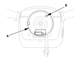
2.
|
Center the cable reel (A). Do this by first rotating the cable
reel clockwise until it stops.
|
|
3.
|
Rotate the cable reel counterclockwise about three full turns.
The arrow mark (B) on the cable reel label should point straight
up.
|
|
|
|
|
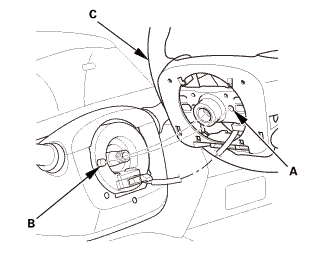
4.
|
Position the steering wheel hub (A) so that it engages the pin
(B) of the cable reel.
|
|
5.
|
Install the steering wheel (C) on to the steering column shaft.
|
|
NOTE: Do not tap on the steering wheel or the steering column
shaft when installing the steering wheel.
|
|
|
 no no
|
|
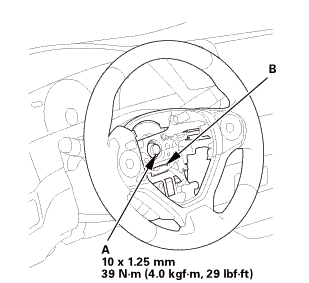
6.
|
Install the steering wheel bolt (A), and tighten it to the specified
torque.
|
|
7.
|
Connect the connector (B).
|
|
8.
|
Make sure the wire harness is routed and fastened properly.
|
|
|
 mmmmin)in! mmmmin)in!
|
|
NOTE: If you are replacing a deployed driver's airbag, inspect
the cable reel for heat damage. If there is any damage, replace
the cable reel.
|
|
1.
|
Place the driver's airbag (A) in the steering wheel.
|
|
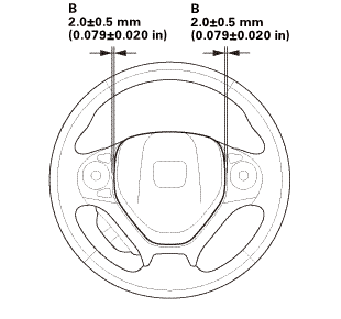
2.
|
Tighten the new TORX bolts using a TORX T30 bit.
|
|
NOTE: Make sure the clearance (B) between the steering wheel
and horn pad is the specified value.
|
|
|

|
|
3.
|
Connect the driver's airbag inflator connector (A) on the cable
reel harness.
|
|
4.
|
Connect the horn switch connector (B).
|
|
NOTE: After reconnecting the negative cable to the battery, make
sure the horn works properly.
|
|
5.
|
Install the access panel (C).
|
|
| 11. |
Battery Terminal (SRS) - Reconnection |
|
 (o.2ao.sam. (o.2ao.sam.
|
|
NOTE: If the battery performs abnormally, test the battery.
|
|
1.
|
Clean the battery terminals.
|
|
2.
|
Connect the positive cable (A) to the battery.
|
|
NOTE: Always connect the positive side first.
|
|
3.
|
Connect the negative cable and the battery sensor (B) to the
battery.
|
|
NOTE: To protect the battery sensor connector (C) from damage,
do not hold it when installing the negative terminal.
|
|
4.
|
Apply multipurpose grease to the terminals to prevent corrosion.
|
|
| 12. |
Confirm Proper SRS Operation |
|
|
Turn the ignition switch to ON (II), and check that the SRS indicator
comes on for about 6 seconds and then goes off.
|
|
| 13. |
Steering After Install - Check |
|
|
1.
|
After installation, check these items:
|
|
|
Start the engine, allow it to idle, and turn
the steering wheel from lock to lock several times.
|
|
|
|
Check that the EPS indicator does not come on.
|
|
|
|
Check the steering wheel spoke angle. If steering
spoke angles to the right and left are not equal
(steering wheel and rack are not centered), correct
the engagement of the joint/pinion shaft splines.
|
|
|
|
| 14. |
Front Toe - Inspection |
|
|
Use commercially available computerized four wheel alignment
equipment to measure wheel alignment (caster, camber, toe, and turning
angle). Follow the equipment manufacturer's instructions.
|
|
1.
|
Set the steering column to the middle tilt position and telescopic
positions.
|
|
2.
|
Center the steering wheel spokes, and install a steering wheel
holder tool.
|
|
3.
|
Check the toe with the wheels pointed straight ahead.
|
|
Front toe-in: 0±2 mm (0±0.08 in)
|
|
|
If adjustment is required, go to the front toe
adjustment.
|
|
|
|
If no adjustment is required, remove the alignment
equipment.
|
|
|
|
|
|
|
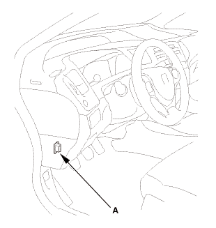
1.
|
Connect the HDS to the data link connector (DLC) (A) located
under the driver's side of the dashboard.
|
|
2.
|
Turn the ignition switch to ON (II).
|
|
3.
|
Make sure the HDS communicates with the vehicle. If it does not
communicate, go to the DLC circuit troubleshooting.
|
|
| 16. |
VSA Sensor Neutral Position - Memorization |
|
|
1.
|
Park the vehicle on a flat and level surface, with the steering
wheel in the straight ahead position.
|
|
2.
|
Select VSA ADJUSTMENT, then select ALL SENSORS with the HDS,
and follow the screen prompts.
|
|
NOTE: See the HDS Help menu for specific instructions.
|
|
| 17. |
Steering Angle Sensor Neutral Position - Clear |
|
|
1.
|
Select EPS ADJUSTMENT, then select EPS STEERING ANGLE SENSOR
VALUE CLEAR and follow the screen prompts on the HDS.
|
|
NOTE: See the HDS Help menu for specific instructions.
|
|
5111A8 LEFT
5111A9 RIGHT
5111B0 BOTH
1.
Vehicle Lift
1.
Raise the vehicle on a lift, and make sure it is securely sup ...
Disassembly
1.
HFL Switch
1.
Remove the lid (A).
2.
...
See also:
Honda Civic Owners Manual. Audio System Theft Protection
The audio system is disabled when it is disconnected from the power source,
such as
when the battery is disconnected or goes dead. In certain conditions, the system
may display a code entry screen. If this occurs, reactivate the audio system.
Reactivating the audio system
1. Turn the ignition ...
 Steering Tie-Rod End Ball Joint Boot Replacement
 Steering Wheel Disassembly and Reassembly