|
|
OPDS Sensor Initialization
|
|
When you replace a front passenger's seat-back cover/pad, the
SRS unit, and/or the ODS unit, initialize the OPDS sensor with the
HDS.
|
|

|
A new (uninitialized) ODS unit installed with a faulty
OPDS sensor (DTC 86-1x or 86-2x) can cause DTCs 85-71 and
85-78. If the SRS has a hard DTC 86-1x or 86-2x, troubleshoot
the DTCs completely before replacing the ODS unit.
|
|
|
|
Make sure all components of the front passenger's seat
are correctly installed.
|
|
|
|
Make sure nothing is on the front passenger's seat, including
aftermarket seat covers or mats.
|
|
|
|
Make sure there is nothing in the front passenger's seat-back
pocket.
|
|
|
|
Dehumidify inside of the vehicle with A/C.
|
|
|
1.
|
Set the seat-back in a normal position.
|
|
2.
|
From the HDS Main Menu, select SRS, then INITIALIZATION. In the
INITIALIZATION Menu, select ODS Initialization. Follow the prompts
until the OPDS sensor initialization has been completed.
|
|
3.
|
Turn the ignition switch to LOCK (0), then wait for 10 seconds.
|
|
NOTE: If the ODS unit fails to initialize after several attempts,
replace the seat-back cover/pad equipped with an OPDS sensor, and
retry. If the ODS unit continues to fail to initialize, replace
the ODS unit.
|
| Front Passenger's Weight Sensor Initialization
|
|
When you replace the SRS unit, the front passenger's weight sensor,
the front passenger's seat frame, front passenger's seat rail, or
the ODS unit, initialize the front passenger's weight sensor with
the HDS.
|
|
|
Make sure all components of the front passenger's seat
are correctly installed.
|
|
|
|
Make sure nothing is on the front passenger's seat, including
after market seat covers or mats.
|
|
|
|
Make sure there is nothing in the front passenger's seat-back
pocket.
|
|
|
|
Keep the windows and the moonroof closed.
|
|
|
|
Make sure the vehicle is on level ground.
|
|
|
|
Dehumidify inside of the vehicle with A/C.
|
|
|
|
Do not touch the front passenger's seat during the operation
check.
|
|
|
|
Do not expose the front passenger's seat to sudden temperature
changes.
|
|
|
1.
|
Position the front passenger's seat all the way rearward, and
adjust the seat-back to the forward most position. Do not move the
seat from this position until the initialization is completed.
|
|
2.
|
Drive the vehicle, and accelerate to 22 mph (36 km/h), then stop
on level ground.
|
|
3.
|
From the HDS Main Menu, select SRS, then INITIALIZATION. In the
INITIALIZATION Menu, select SWS Initialization. Follow the prompts
until the front passenger's weight sensor initialization has been
completed.
|
|
4.
|
Turn the ignition switch to LOCK (0).
|
|


 n-m
n-m

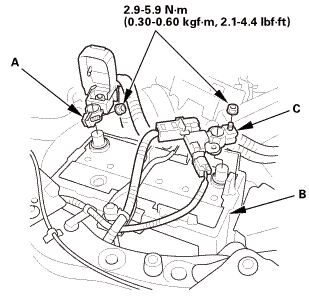 (o.2ao.sam.
 SRS Component Replacement/Inspection After Deployment ('13-'14)
 Airbag and Tensioner Disposal - in the Vehicle ('13-'14)