Honda Civic Service Manual: Right M/T Differential Oil Seal Replacement (R18Z1 M/T)
2191F5 RIGHT

| 1. | Vehicle Lift |
|
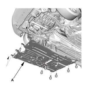
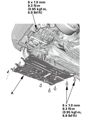
| 2. | Engine Undercover |
|
|
|
| 3. | MTF Replacement |
|
|
|
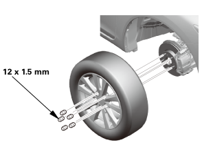
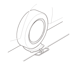
| 4. | Tire and Wheel-Removal, Front Right |
|
|
|
 12x1mm
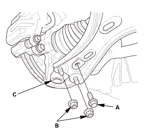
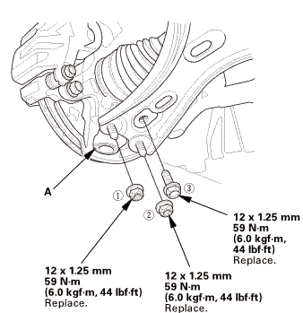
| 5. | Right Lower Ball Joint Lower Arm Side Disconnection |
|
|
|
| 6. | Right Front Driveshaft Inboard Side - Disconnection (With Intermediate Shaft) |
|
|
|
||||||
|
|
|
| 7. | Floor Jack Support (Except K24Z7 Engine) |
|
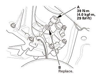
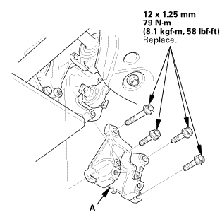
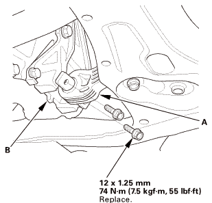
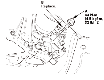
| 8. | Lower Torque Rod - Disconnection |
|
|
|
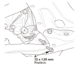
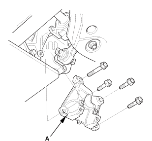
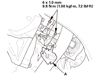
| 9. | Lower Torque Rod Bracket (Except K24Z7 Engine) |
|
|
|
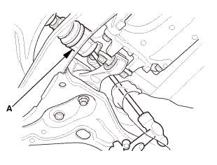
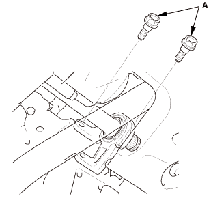
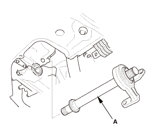
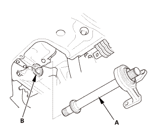
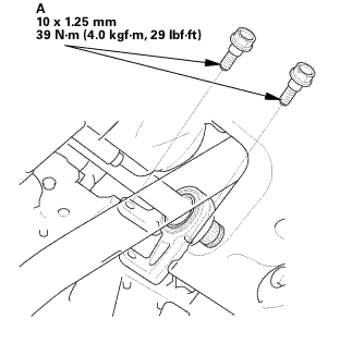
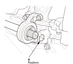
| 10. | Intermediate Shaft Assembly |
|
|
|
|
|
|
|
|
|
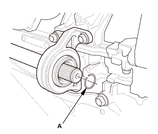
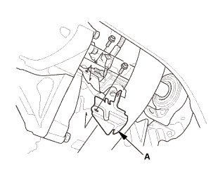
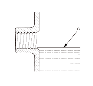
| 11. | M/T Differential Oil Seal, Right |
|
|
|
||||||
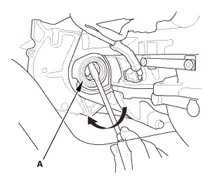

| 1. | M/T Differential Oil Seal, Right |
|
|
|

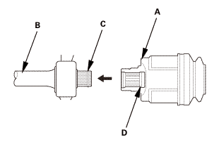
| 2. | Intermediate Shaft Assembly |
|
|
|
||||||
|
|
|
 mmu....
|
|
|
 mms.
mms.| 3. | Lower Torque Rod Bracket (Except K24Z7 Engine) |
|
|
|
 mmmn
mmmn| 4. | Lower Torque Rod - Reconnection |
|
|
|
| 5. | Floor Jack Support (Except K24Z7 Engine) |
|
| 6. | Right Front Driveshaft Inboard Side - Reconnection (With Intermediate Shaft) |
|
|
|
|
|
|
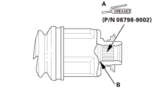 (p/n
(p/n|
|
|
 ei
ei| 7. | Right Lower Ball Joint Lower Arm Side Reconnection |
|
|
|
 replace.
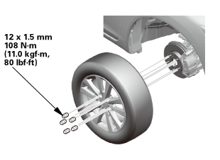
| 8. | Tire and Wheel-Installation, Front Right |
|
|
|
||||||
 mminmuan
| 9. | Driveshaft After Install Check |
|
| 10. | MTF Replacement |
|
|
|
||||||||||||||||||||||||||
| 11. | Engine Undercover |
|
|
|
| 12. | Pre-Alignment Checks |
|
| 13. | Caster - Inspection |
|
|||||||||||||||||||||||||||||||||||||||||||||||

| 14. | Camber - Inspection |
|
||||||||||||||||||||||||||||||||||||||||||||||||||||||||||||||||||||||||||||||||||||||
| 15. | Front Toe - Inspection |
|
|||||||||||||||||||||||||
| 16. | Turning Angle - Inspection |
|
|
|
|||||||||||||||||||||||||||||||||||||||||||||||||||||||||||||||||||||||||||||||||||||||||
|
|
|
|||||||||||||||||||||||||||||||||||||||||||||||||||||||||
| 17. | Test Drive |
|
| 18. | Maintenance Minder Reset |
|
 Right A/T Differential Oil Seal Replacement (A/T)
2191M0 RIGHT
1.
Vehicle Lift
1.
Raise the vehicle on a lift, and make sure it is securely supported.
...
 M/T Differential Carrier and Final Driven Gear Removal and Installation (K24Z7)
2311F1
Removal
1.
M/T Change Lever Assembly
1.
Remove the interlock bolt (A).
...
See also:
Honda Civic Service Manual. Rear Speaker Removal, Installation, and Test (2-door)
013100 LEFT REAR
0131A8 RIGHT REAR
Removal
NOTE: SRS components are located in this area. Review the SRS
component locations and the precautions and procedures before doing
repairs or service.
1.
Both Quarter Pi ...
