Honda Civic Service Manual: Rear Trailing Arm Removal and Installation (Natural Gas models)

|
|
1.
|
Raise the vehicle on a lift, and make sure it is securely supported.
|
|
|
|
|
1.
|
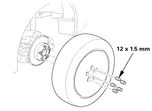
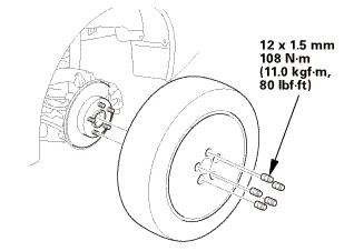
Remove the rear wheel.
|
|
| 3. |
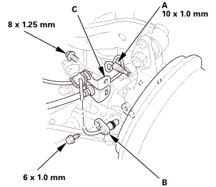
Rear Wheel Speed Sensor, Brake Hose Mounting Bracket, and Brake Line |
|
|

Do not spill brake fluid on the vehicle; it may damage the paint. If
brake fluid gets on the paint, wash it off immediately with water.
|
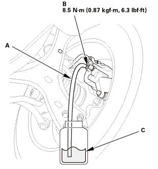
1.
|
Disconnect the brake line (A) from the wheel cylinder.
|
|
NOTE: After removal, plug the ends of the hoses and the joints
to prevent spilling brake fluid.
|
|
2.
|
Remove the wheel speed sensor (B).
|
|
NOTE: Do not disconnect the wheel speed sensor connector.
|
|
3.
|
Remove the brake hose mounting bracket (C).
|
|
| 4. |
Rear Knuckle - Jack Up |
|
|
|
1.
|
Position a floor jack at the connecting point of the trailing
arm (A) and the knuckle (B).
|
|
2.
|
Raise the floor jack until the suspension begins to compress.
|
|
| 5. |
Rear Damper Lower Side - Disconnection |
|
|
|
1.
|
Remove the damper mounting bolt (A).
|
|
| 6. |
Rear Upper Arm Knuckle Side - Disconnection |
|
 i2xi2inln i2xi2inln
|
|
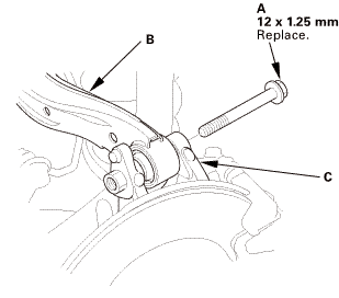
1.
|
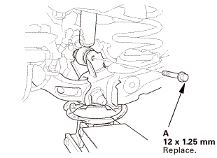
Remove the flange bolt (A).
|
|
2.
|
Disconnect the upper arm (B) from the knuckle (C).
|
|
| 7. |
Rear Trailing Arm Knuckle Side - Disconnection |
|
|
|
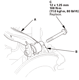
1.
|
Mark the cam positions of the adjusting bolt (A) with the frame.
|
|
2.
|
Mark the cam positions of the adjusting cam plate (B) with the
frame.
|
|
3.
|
Remove the self-locking nut (C), the adjusting cam plate, and
the adjusting bolt.
|
|
4.
|
Remove the flange bolt (D).
|
|
5.
|
Disconnect the knuckle from the trailing arm.
|
|
| 8. |
Stabilizer Link Trailing Arm Side - Disconnection |
|
|
|
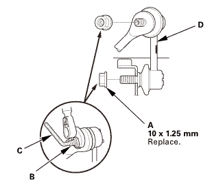
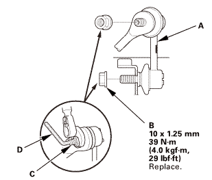
1.
|
Remove the flange nut (A) while holding the respective joint
pin (B) with a hex wrench (C).
|
|
2.
|
Disconnect the stabilizer link (D) from the trailing arm.
|
|
|
|
|
1.
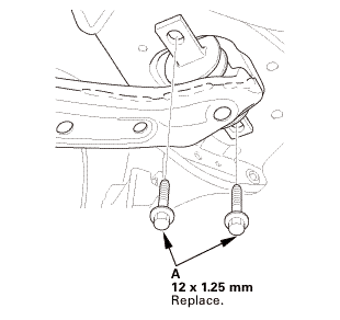
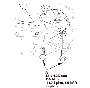
|
Remove the trailing arm front mounting bolts (A).
|
|
2.
|
Lower the floor jack gradually.
|
|
|
|
|
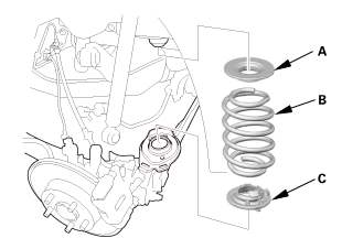
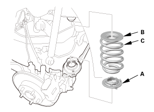
3.
|
Remove the spring mounting cushion (A).
|
|
4.
|
Remove the spring (B).
|
|
5.
|
Remove the lower spring seat (C).
|
|
|
|
|
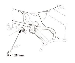
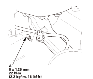
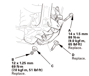
1.
|
Remove the parking brake cable mounting bolt (A).
|
|
|
 12x11mm 12x11mm
|
|
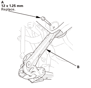
2.
|
Remove the trailing arm rear mounting bolt (A).
|
|
3.
|
Lower the jack, and remove the trailing arm (B).
|
|

|
|
|
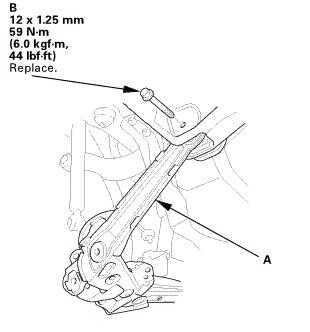
1.
|
Install the trailing arm (A).
|
|
2.
|
Loosely install the new trailing arm rear mounting bolt (B).
|
|
|
 125mm22 125mm22
|
|
3.
|
Install the parking brake cable mounting bolt (A).
|
|
|
|
|
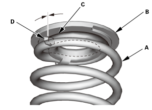
1.
|
Install the spring (A) on the spring mounting cushion (B) by
aligning the upper end (C) of the spring with the ledge portion
(D) of the spring mounting cushion.
|
|
|
|
|
2.
|
Install the lower spring seat (A).
|
|
3.
|
Install the spring mounting cushion (B) and the spring (C).
|
|
|
|
|
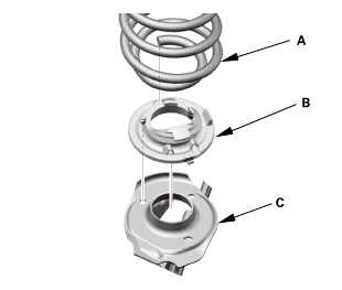
4.
|
Align the bottom of the spring (A) and the lower spring seat
(B) with the trailing arm (C) as shown.
|
|
|
 mmh5ummn)replace. mmh5ummn)replace.
|
|
5.
|
Loosely install the new trailing arm front mounting bolts (A).
|
|
| 3. |
Stabilizer Link Trailing Arm Side - Reconnection |
|
 125mmm,29 125mmm,29
|
|
1.
|
Connect the stabilizer link (A) to the trailing arm.
|
|
2.
|
Install the new flange nut (B), and tighten them to the specified
torque while holding the respective joint pin (C) with a hex wrench
(D).
|
|
| 4. |
Rear Trailing Arm Knuckle Side - Reconnection |
|
 ....n-m65....5n.m(m ....n-m65....5n.m(m
|
|
1.
|
Connect the knuckle to the trailing arm.
|
|
2.
|
Loosely install the new flange bolt (A).
|
|
3.
|
Loosely install the new self-locking nut (B), the adjusting cam
plate (C), and the new adjusting bolt (D).
|
|
NOTE: Align the cam positions of the adjusting bolt and the adjusting
cam plate with the marked positions when tightening the self-locking
nut.
|
|
| 5. |
Rear Upper Arm Knuckle Side - Reconnection |
|
 125mmumngvum 125mmumngvum
|
|
1.
|
Connect the upper arm (A) to the knuckle (B).
|
|
2.
|
Loosely install the new flange bolt (C).
|
|
| 6. |
Rear Damper Lower Side - Reconnection |
|
|
|
1.
|
Loosely install the new damper mounting bolt (A).
|
|
| 7. |
Rear Suspension All Mounting - Tighten Under Vehicle's Weight |
|
|
1.
|
Raise the rear suspension with a floor jack to load the vehicle
weight.
|
|
2.
|
Tighten all mounting hardware to the specified torque.
|
|
| 8. |
Rear Wheel Speed Sensor, Brake Hose Mounting Bracket, and Brake Line |
|
|
|
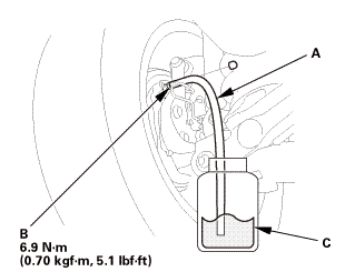
1.
|
Install the brake hose mounting bracket (A).
|
|
2.
|
Install the wheel speed sensor (B).
|
|
3.
|
Connect the brake line (C) to the wheel cylinder.
|
|
| 9. |
Brake System - Bleeding (Natural Gas Model) |
|
|
Do not spill brake fluid on the vehicle; it may damage the paint. If
brake fluid does contact the paint, wash it off immediately with water.
|

|
Do not reuse the drained fluid. Use only new Honda DOT
3 Brake Fluid from an unopened container. Using a non-Honda
brake fluid can cause corrosion and shorten the life of
the system.
|
|
|
|
Make sure no dirt or other foreign matter gets in the
brake fluid.
|
|
|
|
The reservoir connected to the master cylinder must be
at the MAX (upper) level mark at the start of the bleeding
procedure and checked after bleeding each wheel. Add fluid
as required.
|
|
|
|
There are three different methods used for bleeding brake
systems. The method shown here is the preferred manual method
for removing the air from the system. For pressure or vacuum
bleeding, refer to tool manufacturer's instructions included
with the tool.
|
|
|
1.
|
Make sure the brake fluid level in the reservoir tank (A) is
at the MAX (upper) level line (B).
|
|
|
 sznuzucz sznuzucz
|
|
2.
|
Start the bleeding at the driver's side of the front brake system.
|
|
NOTE: Bleed the calipers in the sequence shown.
|
|
|
Front
 x.sm.x1imm x.sm.x1imm
Rear
|
|
3.
|
Attach a length of clear drain tube (A) to the bleed screw (B).
|
|
4.
|
Submerge the other end of the drain tube into a clear plastic
catch bottle of brake fluid (C).
|
|
5.
|
Have an assistant slowly pump the brake pedal several times then
apply steady continuous pressure.
|
|
6.
|
Loosen the bleed screw slowly to bleed the fluid into the plastic
catch bottle. The brake pedal will travel toward the floor as the
fluid is bled from the system.
|
|
7.
|
When the brake pedal reaches the floor, have the assistant hold
the pedal in that position, then tighten the bleed screw. The brake
pedal can now be released.
|
|
8.
|
Check and refill the master cylinder reservoir tank to the MAX
(upper) level line. Be sure to reinstall the master cylinder reservoir
cap.
|
|
9.
|
Repeat steps 5 thru 8 until the brake fluid in the clear drain
tube appears fresh and there are no air bubbles in the fluid.
|
|
10.
|
Repeat this procedure for each brake in the bleeding sequence.
|
|
|
 15mmumum 15mmumum
|
|
1.
|
Install the rear wheel.
|
|
NOTE: Before installing the wheel, clean the mating surfaces
between the brake disc or the brake drum and the inside of the wheel.
|
|
|
|
For proper inspection and adjustment of the wheel alignment,
do these checks:
|
|
1.
|
Release the parking brake to avoid an incorrect measurement.
|
|
2.
|
Make sure the suspension is not modified.
|
|
3.
|
Make sure the fuel tank is full, and that the tire repair kit,
the spare tire, the jack, and the tools are in place on the vehicle.
|
|
4.
|
Check the tire size and tire pressure according to tire information.
|
|
|
|
Use commercially available computerized four wheel alignment
equipment to measure wheel alignment (caster, camber, toe, and turning
angle). Follow the equipment manufacturer's instructions.
|
|
1.
|
Check the camber angle.
|
|
USA and Canada models
|
Camber angle:
|
| |
Except Si:
|
| |
|
Front:
|
0 ° 00 ’±30 ’
|
| |
|
Rear:
|
-0 ° 45 ’±45 ’
|
| |
Si (Without 18 inch wheel):
|
| |
|
Front:
|
-0 ° 04 ’±30 ’
|
| |
|
Rear:
|
-0 ° 52 ’±45 ’
|
| |
Si (With 18 inch wheel):
|
| |
|
Front:
|
-0 ° 18 ’±30 ’
|
| |
|
Rear:
|
-0 ° 45 ’±45 ’
|
|
(Maximum difference between the front right and
left side: 0 ° 45 ’)
|
|
|
|
|
Mexico models
|
Camber angle:
|
| |
Front:
|
0 ° 20 ’±30 ’
|
| |
Rear:
|
-0 ° 22 ’±45 ’
|
|
(Maximum difference between the front right and
left side: 0 ° 45 ’)
|
|
|
|
|
|
If the measurement is within specification, measure
the toe-in.
|
|
|
|
If the measurement for the front camber is not
within the specification, go to front camber adjustment.
|
|
|
|
If the measurement for the rear camber is not
within the specification, check for bent or damaged
suspension components.
|
|
|
|
| 13. |
Rear Toe - Inspection |
|
|
Use commercially available computerized four wheel alignment
equipment to measure wheel alignment (caster, camber, toe, and turning
angle). Follow the equipment manufacturer's instructions.
|
|
1.
|
Release the parking brake to avoid an incorrect measurement.
|
|
2.
|
Check the toe.
|
|
Rear toe-in: 2+2-1 mm (0.08+0.08-0.04 in)
|
|
|
If adjustment is required, go to the rear toe
adjustment.
|
|
|
|
If no adjustment is required, go to front toe
inspection.
|
|
|
|
|
|
1.
|
Test-drive the vehicle.
|
|
| 15. |
Rear Stabilizer Link - Tighten |
|
|
1.
|
After 5 minutes of driving, torque the self-locking nut again
to the specified torque.
|
|
1.
Vehicle Lift
1.
Raise the vehicle on a lift, and make sure it is securely supported.
2. ...
416118 LEFT
416119 RIGHT
416117 BOTH
1.
Vehicle Lift
1.
Raise the vehicle on a lift, and make sure it is securely sup ...
See also:
Honda Civic Owners Manual. Front Seat Heaters
The ignition switch must be in ON (w*1 to use
the seat heaters
Press the seat heater button:
Once - The HI setting (three indicators on)
Twice - The MID setting (two indicators on)
Three times - The LO setting (one indicator on)
Four times - The OFF setting (no indicators on)
*1: Mode ...
 Rear Trailing Arm Removal and Installation (Drum Brake except Natural Gas models)
 Front Lower Arm Removal and Installation