Honda Civic Service Manual: Intake Manifold Removal and Installation (R18A9)
 View
View
| 1. | Intake Manifold Exploded View (Natural Gas Model) |
|
Exploded View |

Removal
|
NOTE: Refer to the Exploded View if needed during this procedure. |
| 1. | Fuel Pressure - Relieving (Between the engine and the manual shut-off valve) (Natural Gas Model) |
|
|
Compressed natural gas is flammable and highly explosive. You could be
killed or seriously injured if leaking natural gas is ignited.
|
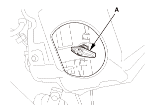

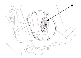
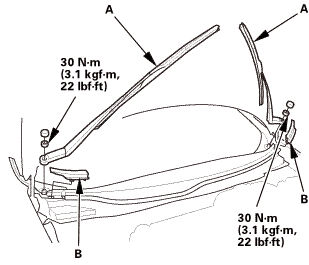
| 2. | Wiper Arm Assembly |
|
|
|
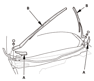
| 3. | Both Side Cowl Covers |
|
|
|
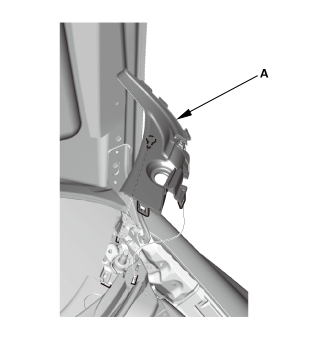
| 4. | Center Cowl Cover |
|
|
|

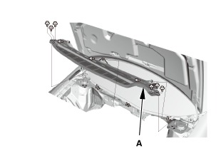
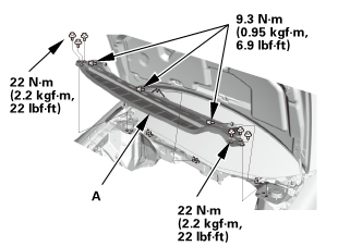
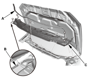
| 5. | Under Cowl Panel |
|
|
|
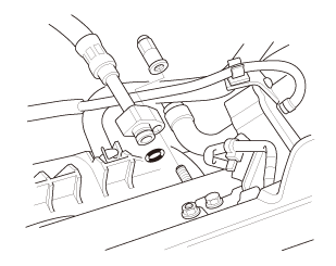
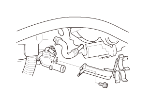
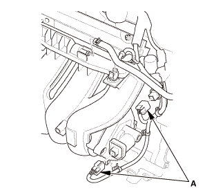
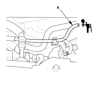
| 6. | Fuel Feed Hose (Natural Gas Model) |
|
|
|
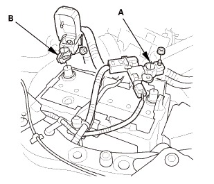
| 7. | Battery Terminal - Disconnection |
|
|
|
||||||||||||
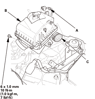
| 8. | Air Cleaner |
|
|
|
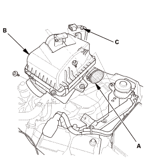
| 9. | Intake Air Duct |
|
|
|
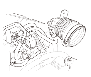
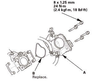
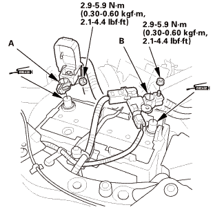
| 10. | Throttle Body - Remove (Natural Gas Model) |
|
|
|
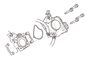
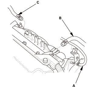
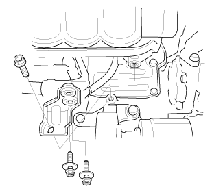
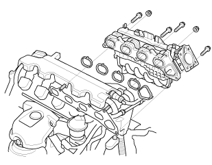
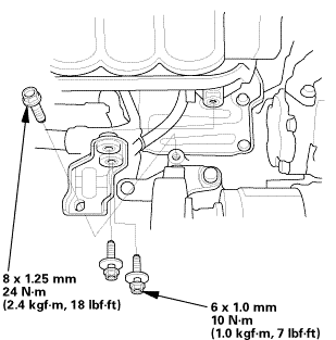
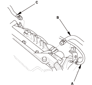
| 11. | Intake Manifold Assembly (Natural Gas Model) |
|
|
|
|
|
|
|
|
|
|
|
|
|
|
|

Installation
|
NOTE: Refer to the Exploded View if needed during this procedure. |
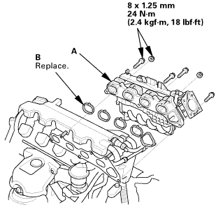
| 1. | Intake Manifold Assembly (Natural Gas Model) |
|
|
|
 mm
mm|
|
|
|
|
|
|
|
|

|
|
|
| 2. | Throttle Body - Install (Natural Gas Model) |
|
|
|
 mmm.uimm
| 3. | Intake Air Duct |
|
|
|
| 4. | Air Cleaner |
|
|
|
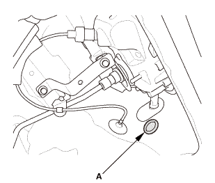
| 5. | Fuel Feed Hose (Natural Gas Model) |
|
|
|

| 6. | Manual Shut-off Valve - Open (Natural Gas Model) |
|
|
|
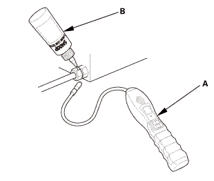
| 7. | Fuel Supply System Leak - Inspection (Natural Gas Model) |
|
|
|
|
|
|
|
|
|
| 8. | Under Cowl Panel |
|
|
|
 22mm)2222
| 9. | Center Cowl Cover |
|
|
|
| 10. | Both Side Cowl Covers |
|
|
|
| 11. | Wiper Arm Assembly |
|
|
|
 1.122
1.122| 12. | Battery Terminal - Reconnection |
|
|
|
||||||||||||||||
| 13. | Tubes, Hoses, and Connectors After Installation Check |
|
 Intake Manifold Removal and Installation (K24Z7)
1111C1
View
1.
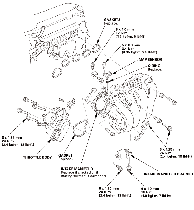
Intake Manifold Exploded View
Exploded View
..iiibasei11mm.ummnu-mnuus.........i22m,mmreplacemaunguuw(i.2kvf-m.l1m1!i25......bracket22...
...
 Intake Manifold Removal and Installation (R18Z1)
View
1.
Intake Manifold Exploded View
Exploded View
max:manifold.msl.mjoinyaonvmanifoldivorivmulinv
Removal
NOTE: Refer to the Exploded Vi ...
See also:
Honda Civic Owners Manual. Types of Airbags
Your vehicle is equipped with three types of airbags:
Front airbags: Airbags in front of the driver’s and front passenger’s
seats.
Side airbags: Airbags in the driver’s and front passenger’s seat-backs.
Side curtain airbags: Airbags above the side windows.
Each is discussed in ...
