Honda Civic Service Manual: HFL Switch Removal, Installation, and Test
0521B0

Removal
|
NOTE: SRS components are located in this area. Review the SRS component locations and the precautions and procedures before doing repairs or service. |
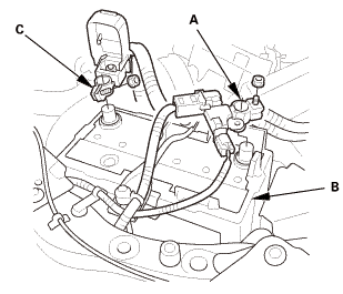
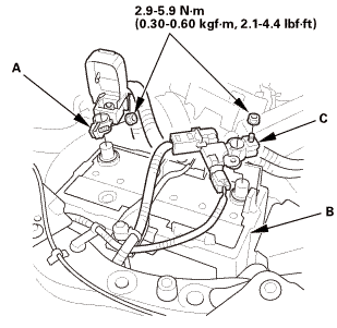
| 1. | Battery Terminal (SRS) - Disconnection |
|
|
|
|||||||||||||||
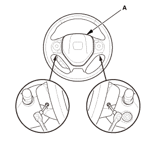
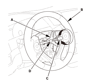
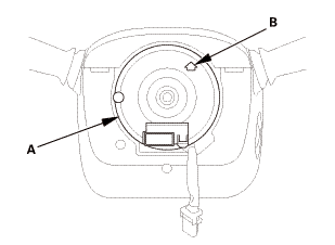
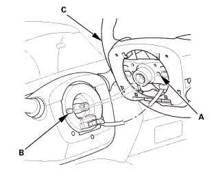
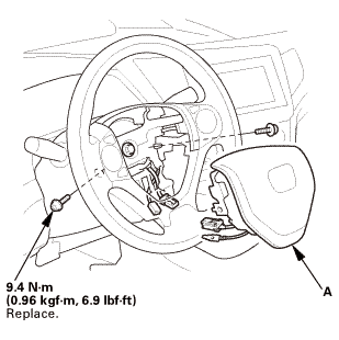
| 2. | Driver's Airbag |
|
|
|
|
|
|
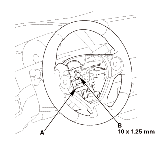
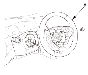
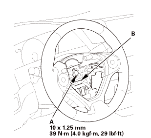
| 3. | Steering Wheel Assembly |
|
|
|
 wxusmm
|
|
|
||||||||||||||||||||

|
|
|
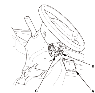
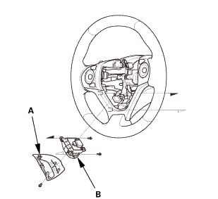
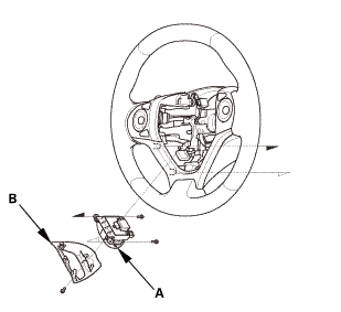
| 4. | HFL Switch |
|
|
|
 Test
Test
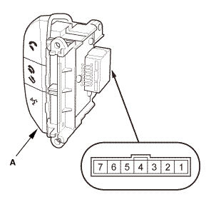
| 1. | HFL Switch - Test |
|
|
|
|||||||||||||||||||||

Installation
|
NOTE: SRS components are located in this area. Review the SRS component locations and the precautions and procedures before doing repairs or service. |
| 1. | HFL Switch |
|
|
|
| 2. | Steering Wheel Assembly |
|
|
|
|
|
|
|||||||||
|
|
|
 no
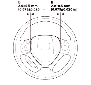
no| 3. | Driver's Airbag |
|
|
|
||||||||||
 mmmmin)in!
|
|
|
||||||||||||

| 4. | Battery Terminal (SRS) - Reconnection |
|
|
|
||||||||||||||||
 (o.2ao.sam.
| 5. | HDS DLC - Connection |
|
|
|

| 6. | VSA Sensor Neutral Position - Memorization |
|
||||||||||
| 7. | Steering Angle Sensor Neutral Position - Clear |
|
|||||||

 HandsFreeLink Control Unit Removal and Installation
0521B3
Removal
NOTE:
SRS components are located in this area. Review the SRS component
locations and the pre ...
See also:
Honda Civic Service Manual. Front Power Window Motor Removal and Installation (4-door)
744160 LEFT FRONT
744170 RIGHT FRONT
Removal
1.
Front Door Power Window Switch Panel (4-door)
1.
Remove the power window switch panel (A).
2.
Front Door Panel - ...
