Honda Civic Service Manual: Front Wheel Bolt Removal and Installation (Si models)

|
|
1.
|
Raise the vehicle on a lift, and make sure it is securely supported.
|
|
|
|
|
1.
|
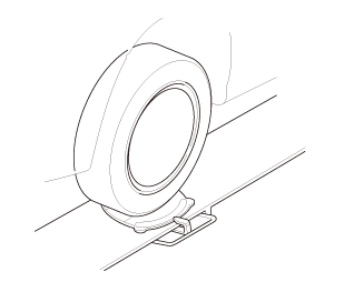
Remove the front wheel.
|
|
| 3. |
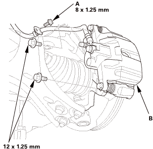
Front Brake Caliper - Detach |
|
 115mm 115mm
|
|
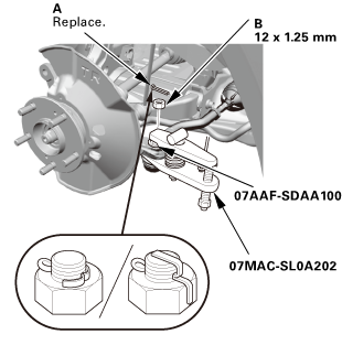
1.
|
Remove the brake hose mounting bolt (A).
|
|
2.
|
Remove the caliper assembly (B).
|
|
NOTE:
|
|

|
To prevent damage to the caliper assembly or
brake hose, use a short piece of wire to hang the
caliper assembly from the undercarriage.
|
|
|
|
Do not twist the brake hose excessively.
|
|
|
|
| 4. |
Front Wheel Speed Sensor - Move |
|
|
|
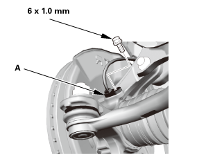
1.
|
Remove the wheel speed sensor (A).
|
|
NOTE: Do not disconnect the wheel speed sensor connector.
|
|
| 5. |
Driveshaft Spindle Nut, Front Left |
|
|
|
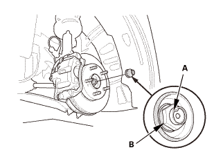
1.
|
Pry up the stake (A) on the spindle nut (B).
|
|
2.
|
Remove the spindle nut.
|
|
|
|
|
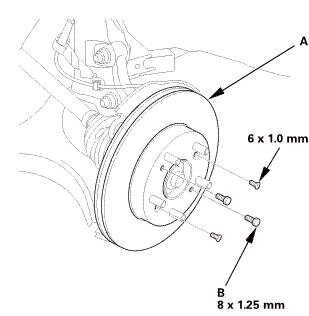
1.
|
Remove the brake disc (A).
|
|
NOTE: If the brake disc is stuck to the front hub, thread two
8 x 1.25 mm bolts (B) into the brake disc to push it away from the
front hub. Turn each bolt 90 degrees at a time to prevent the brake
disc from binding.
|
|
|
|

Always use a ball joint remover to disconnect a ball joint. Do not strike
the housing or any other part of the ball joint connection to disconnect
it.
|
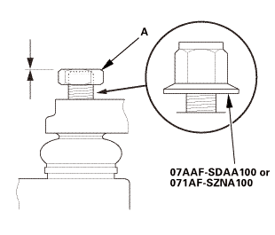
1.
|
Install a hex nut (A) or the ball joint thread protector.
|
|
NOTE: When using a hex nut, make sure the nut is flush with the
ball joint pin end to prevent damage to the threaded end of the
ball joint pin.
|
|
|
 ov ov
|
|
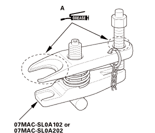
2.
|
Apply grease to the ball joint remover on the areas shown (A).
|
|
|
 wmae-sldaidz wmae-sldaidz
|
|
3.
|
Install the ball joint remover as shown.
|
|
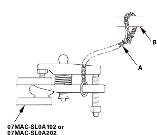
NOTE:
|
|
|
Fasten the safety chain (A) securely to a suspension
arm or the subframe (B).
|
|
|
|
Making sure not to damage the ball joint boot.
|
|
|
|
4.
|
Tighten the pressure bolt until the ball joint pin pops loose
from the ball joint connecting hole.
|
|
NOTE: Do not use pneumatic or electric tools on the pressure
bolt.
|
|
5.
|
Remove the ball joint remover.
|
|
6.
|
Remove the hex nut or the ball joint thread protector.
|
|
7.
|
Pull the ball joint out of the ball joint connecting hole.
|
|
| 8. |
Tie-Rod End Ball Joint - Disconnection |
|
|
|
1.
|
Remove the cotter pin (A).
|
|
3.
|
Disconnect the tie-rod end ball joint.
|
|
| 9. |
Lower Ball Joint Lower Arm Side - Disconnection |
|
 i225 i225
|
|
1.
|
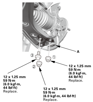
Remove the flange bolt (A).
|
|
2.
|
Remove the flange nuts (B).
|
|
3.
|
Disconnect the lower ball joint (C) from the lower arm.
|
|
| 10. |
Front Knuckle/Hub Assembly |
|
 v\r.n.v\r.n.ii v\r.n.v\r.n.ii
|
|
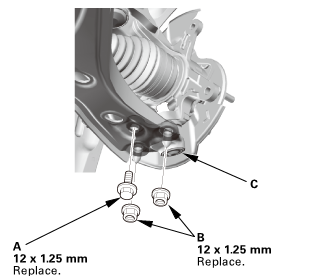
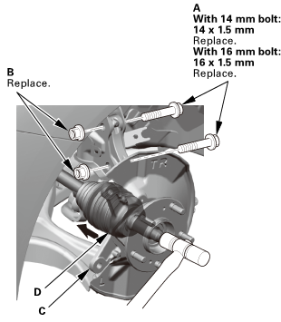
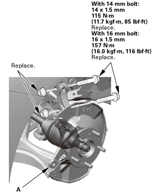
1.
|
Remove the damper pinch bolts (A) and the flange nuts (B).
|
|
2.
|
Pull the knuckle (C) outward, and separate the outboard joint
(D) from the front hub, then remove the knuckle/hub.
|
|
NOTE: Do not pull the driveshaft end outward. The inner driveshaft
inboard joint may come apart.
|
|
| 11. |
Front Lower Ball Joint |
|
|
|
1.
|
Remove the lock pin (A).
|
|
2.
|
Remove the castle nut (B).
|
|
3.
|
Remove the lower ball joint (C).
|
|
|
 i7.wheelo7gafsma1oo i7.wheelo7gafsma1oo
|
|
1.
|
Separate the hub (A) from the knuckle (B).
|
|
NOTE: Be careful not to damage or deform the splash guard (C).
|
|
|
 pun17,1:il7gafsei!i)li)il17,1: pun17,1:il7gafsei!i)li)il17,1:
|
|
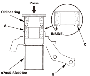
2.
|
Press out the wheel bearing inner race (A) of the hub (B).
|
|
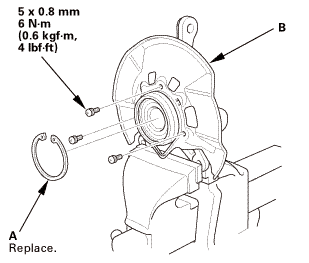
| 13. |
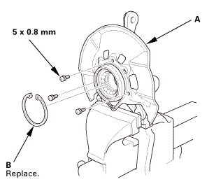
Front Splash Guard and Snap Ring |
|
|
|
1.
|
Remove the splash guard (A).
|
|
2.
|
Remove the snap ring (B).
|
|
|
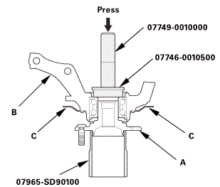
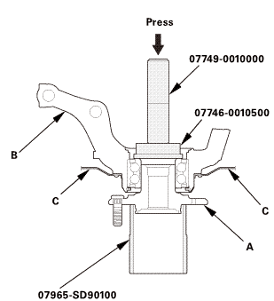
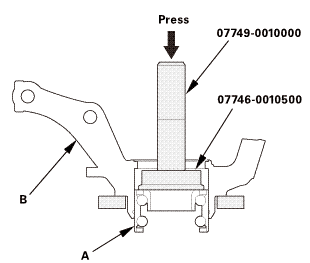 pressn774somosno pressn774somosno
|
|
1.
|
Press the wheel bearing (A) out of the knuckle (B).
|
|
|
|
|
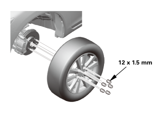
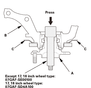
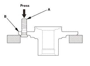
1.
|
Separate the wheel bolt (A) from the hub (B).
|
|

|
NOTE: If you cannot tighten the wheel nut to the specified torque when
installing the wheel, replace the front hub bearing unit as an assembly.
|
|
|
|
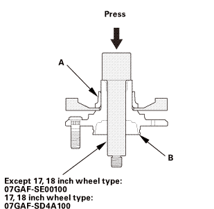
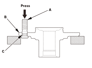
1.
|
Insert the new wheel bolt (A) into the hub (B) while aligning
the splined surfaces (C) on the hub hole with the wheel bolt.
|
|
NOTE:
|
|
|
Degrease the area around the wheel bolt.
|
|
|
|
Make sure the wheel bolt is installed vertically
to the hub disc surface.
|
|
|
|
Before installing the new wheel bolt, clean the
mating surfaces on the bolt and the hub.
|
|
|
|
2.
|
Install the wheel bolt using a hydraulic press until the wheel
bolt shoulder is fully seated.
|
|
|
Except 17, 18 inch wheel type
17, 18 inch wheel type
|
|
1.
|
Wash the knuckle and the hub thoroughly in high flash point solvent
before reassembly.
|
|
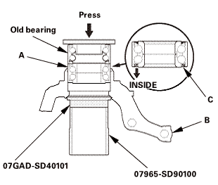
2.
|
Press a new wheel bearing (A) into the knuckle (B).
|
|
NOTE: Install the wheel bearing with the wheel speed sensor magnetic
encoder (C) (brown color) toward the inside of the knuckle.
|
|
| 3. |
Front Splash Guard and Snap Ring |
|
|
|
1.
|
Install the new snap ring (A).
|
|
2.
|
Install the splash guard (B).
|
|
|
Except 17, 18 inch wheel type
17, 18 inch wheel type
 press press
|
|
1.
|
Install the hub (A) onto the knuckle (B).
|
|
NOTE: Be careful not to damage the splash guard (C).
|
|
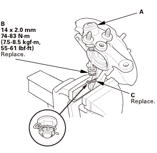
| 5. |
Front Lower Ball Joint |
|
Except 18 inch wheels

18 inch wheel
|
|
1.
|
Install the lower ball joint (A).
|
|
2.
|
Install the new castle nut (B).
|
|
NOTE: Torque the castle nut to the lower torque specification,
then tighten it only far enough to align the slot with the ball
joint pin hole. Do not align the castle nut by loosening it.
|
|
3.
|
Install the lock pin (C) as shown.
|
|
| 6. |
Front Knuckle/Hub Assembly |
|
Except 18 inch wheel
 wmmmmmm115mmm.1immwmmmmmm151mmm,mwu wmmmmmm115mmm.1immwmmmmmm151mmm,mwu
18 inch wheel
 inmminu-m(17.2125 inmminu-m(17.2125
|
|
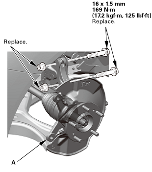
1.
|
Install the knuckle/hub (A).
|
|
NOTE: Apply grease to the mating surfaces of the wheel bearing
and the driveshaft outboard joint.
|
|
| 7. |
Lower Ball Joint Lower Arm Side - Reconnection |
|
 55(ini15mm(skg!m,12x125mm 55(ini15mm(skg!m,12x125mm
|
|
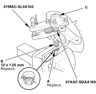
1.
|
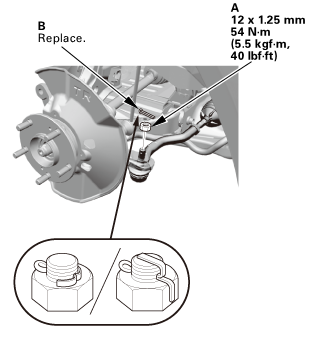
Connect the lower ball joint (A) to the lower arm.
|
|
2.
|
Install the new flange nuts and the new flange bolt in the sequence
shown.
|
|
| 8. |
Tie-Rod End Ball Joint - Reconnection |
|
 i2mmonum i2mmonum
|
|
1.
|
Connect the tie-rod end ball joint.
|
|
3.
|
Install the cotter pin (B) as shown.
|
|
|
|
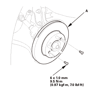
|
1.
|
Install the brake disc (A).
|
|
NOTE: Before installing the brake disc, clean the mating surfaces
between the front hub and the inside of the brake disc.
|
|
| 10. |
Driveshaft Spindle Nut, Front Left |
|
 22x15mm15mm 22x15mm15mm
|
|
1.
|
Apply a small amount of engine oil to the seating surface of
a new spindle nut (A).
|
|
2.
|
Install the spindle nut.
|
|
3.
|
Use a drift to stake the spindle nut shoulder (B) against the
driveshaft.
|
|
| 11. |
Front Wheel Speed Sensor - Move |
|
 lomm lomm
|
|
1.
|
Install the wheel speed sensor (A).
|
|
| 12. |
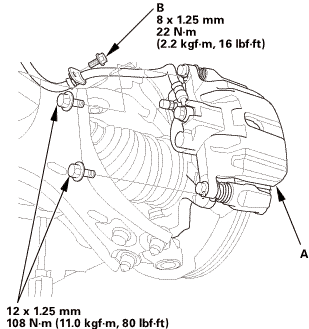
Front Brake Caliper - Reattach |
|
 mm mm
|
|
1.
|
Install the caliper assembly (A).
|
|
2.
|
Install the brake hose mounting bolt (B).
|
|
|
 mmmln-mnomm mmmln-mnomm
|
|
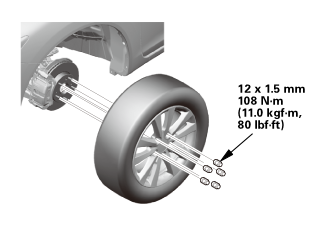
1.
|
Install the front wheel.
|
|
NOTE: Before installing the wheel, clean the mating surfaces
between the brake disc and the inside of the wheel.
|
|
|
|
For proper inspection and adjustment of the wheel alignment,
do these checks:
|
|
1.
|
Release the parking brake to avoid an incorrect measurement.
|
|
2.
|
Make sure the suspension is not modified.
|
|
3.
|
Make sure the fuel tank is full, and that the tire repair kit,
the spare tire, the jack, and the tools are in place on the vehicle.
|
|
4.
|
Check the tire size and tire pressure according to tire information.
|
|
|
|
Use commercially available computerized four wheel alignment
equipment to measure wheel alignment (caster, camber, toe, and turning
angle). Follow the equipment manufacturer's instructions.
|
|
1.
|
Check the caster angle.
|
|
USA and Canada models
|
Caster angle:
|
| |
Except Si:
|
5 ° 19 ’±30 ’
|
| |
Si (Without 18 inch wheel):
|
5 ° 22 ’±30 ’
|
| |
Si (With 18 inch wheel):
|
5 ° 15 ’±30 ’
|
|
|
|
|
Mexico models
|
Caster angle:
|
| |
Without 18 inch wheel:
|
5 ° 10 ’±30 ’
|
| |
With 18 inch wheel:
|
5 ° 6 ’±30 ’
|
|
|
|
|
|
If the measurement is within specifications,
measure the front camber angle.
|
|
|
|
If the measurement is not within specifications,
check for bent or damaged suspension components.
|
|
|
|
|
|
Use commercially available computerized four wheel alignment
equipment to measure wheel alignment (caster, camber, toe, and turning
angle). Follow the equipment manufacturer's instructions.
|
|
1.
|
Check the camber angle.
|
|
USA and Canada models
|
Camber angle:
|
| |
Except Si:
|
| |
|
Front:
|
0 ° 00 ’±30 ’
|
| |
|
Rear:
|
-0 ° 45 ’±45 ’
|
| |
Si (Without 18 inch wheel):
|
| |
|
Front:
|
-0 ° 04 ’±30 ’
|
| |
|
Rear:
|
-0 ° 52 ’±45 ’
|
| |
Si (With 18 inch wheel):
|
| |
|
Front:
|
-0 ° 18 ’±30 ’
|
| |
|
Rear:
|
-0 ° 45 ’±45 ’
|
|
(Maximum difference between the front right and
left side: 0 ° 45 ’)
|
|
|
|
|
Mexico models
|
Camber angle:
|
| |
Front:
|
0 ° 20 ’±30 ’
|
| |
Rear:
|
-0 ° 22 ’±45 ’
|
|
(Maximum difference between the front right and
left side: 0 ° 45 ’)
|
|
|
|
|
|
If the measurement is within specification, measure
the toe-in.
|
|
|
|
If the measurement for the front camber is not
within the specification, go to front camber adjustment.
|
|
|
|
If the measurement for the rear camber is not
within the specification, check for bent or damaged
suspension components.
|
|
|
|
| 17. |
Front Toe - Inspection |
|
|
Use commercially available computerized four wheel alignment
equipment to measure wheel alignment (caster, camber, toe, and turning
angle). Follow the equipment manufacturer's instructions.
|
|
1.
|
Set the steering column to the middle tilt position and telescopic
positions.
|
|
2.
|
Center the steering wheel spokes, and install a steering wheel
holder tool.
|
|
3.
|
Check the toe with the wheels pointed straight ahead.
|
|
Front toe-in: 0±2 mm (0±0.08 in)
|
|
|
If adjustment is required, go to the front toe
adjustment.
|
|
|
|
If no adjustment is required, remove the alignment
equipment.
|
|
|
|
| 18. |
Turning Angle - Inspection |
|
|
|
Use commercially available computerized four wheel alignment
equipment to measure wheel alignment (caster, camber, toe, and turning
angle). Follow the equipment manufacturer's instructions.
|
|
1.
|
Turn the wheel right and left while applying the brake, and measure
the turning angle of both wheels.
|
|
USA and Canada models
|
Turning angle:
|
| |
Except Si:
|
| |
|
Inward:
|
38 ° 30 ’±2 °
|
| |
|
Outward (reference):
|
30 ° 47 ’±1 °
|
| |
Si (Without 18 inch wheel):
|
| |
|
Inward:
|
38 ° 22 ’±2 °
|
| |
|
Outward (reference):
|
30 ° 41 ’±1 °
|
| |
Si (With 18 inch wheel):
|
| |
|
Inward:
|
36 ° 33 ’±2 °
|
| |
|
Outward (reference):
|
29 ° 53 ’±1 °
|
|
|
|
|
Mexico models
|
Turning angle:
|
| |
Without 18 inch wheel:
|
| |
|
Inward:
|
39 ° 12 ’±2 °
|
| |
|
Outward (reference):
|
31 ° 14 ’±1 °
|
| |
With 18 inch wheel:
|
| |
|
Inward:
|
36 ° 58 ’±2 °
|
| |
|
Outward (reference):
|
30 ° 16 ’±1 °
|
|
|
|
|
2.
|
If the measurement is not within the specifications, even up
both sides of the tie-rod threaded section length while adjusting
the front toe.
|
|
3.
|
If it is correct, but the turning angle is not within the specifications,
check for bent or damaged suspension components.
|
|
|
|
|
1.
|
Turn the wheel right and left while applying the brake, and measure
the turning angle of both wheels.
|
|
USA and Canada models
|
Turning angle:
|
| |
Except Si:
|
| |
|
Inward:
|
38 ° 43 ’±2 °
|
| |
|
Outward (reference):
|
30 ° 55 ’±1 °
|
| |
Si:
|
| |
|
Inward:
|
38 ° 36 ’±2 °
|
| |
|
Outward (reference):
|
30 ° 49 ’±1 °
|
|
|
|
|
Mexico models
|
Turning angle:
|
| |
Inward:
|
39 ° 15 ’±2 °
|
| |
Outward (reference):
|
31 ° 21 ’±1 °
|
|
|
|
|
2.
|
If the measurement is not within the specifications, even up
both sides of the tie-rod threaded section length while adjusting
the front toe.
|
|
3.
|
If it is correct, but the turning angle is not within the specifications,
check for bent or damaged suspension components.
|
|
4151B0 LEFT FRONT
4151B1 RIGHT FRONT
1.
Vehicle Lift
1.
Raise the vehicle on a lift, and make sure it is securely suppor ...
1.
Vehicle Lift
1.
Raise the vehicle on a lift, and make sure it is securely supported.
2. ...
See also:
Honda Civic Owners Manual. Checking and Maintaining Wiper Blades
Checking Wiper Blades
If the wiper blade rubber has deteriorated, it will leave streaks and the
hard surfaces
of the blade may scratch the window glass.
Changing the Wiper Blade Rubber
Turn the ignition switch to LOCK 0*1.
While holding the wiper switch in the MIST
position, t ...
 Front Wheel Bolt Removal and Installation (Except Si models)
 Wheel Runout Inspection