Honda Civic Service Manual: Front Lower Ball Joint Removal and Installation
4151B5 LEFT
4151B6 RIGHT
4161C0 BOTH

| 1. | Vehicle Lift |
|
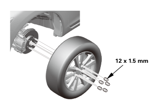
| 2. | Front Wheel |
|
|
|
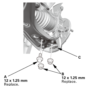
| 3. | Lower Ball Joint Lower Arm Side - Disconnection |
|
|
|
 i225
i225| 4. | Driveshaft Spindle Nut, Front Left |
|
|
|
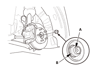
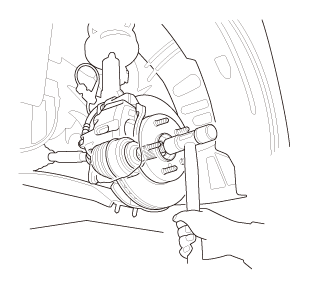
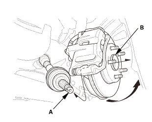
| 5. | Driveshaft Front Left - Disconnection Outboard Side |
|
|
|
|
|
|
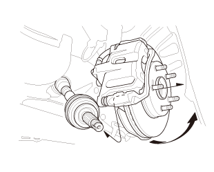
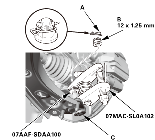
| 6. | Ball Joint - Removal |
|
|
Always use a ball joint remover to disconnect a ball joint. Do not strike the housing or any other part of the ball joint connection to disconnect it.
|
||||||

|
|
|
 ov
ov|
|
|
||||||||||||||||||||||||||||||||
 wmae-sldaidz
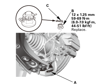
| 7. | Front Lower Ball Joint |
|
|
|

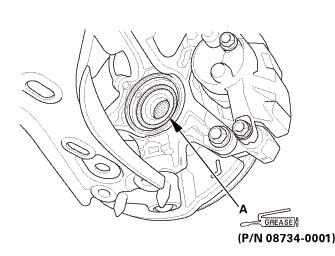
| 1. | Front Lower Ball Joint |
|
Except 18 inch wheel
18 inch wheel
|
|
||||||||||||

| 2. | Driveshaft Front Left - Reconnection, Outboard Side |
|
|
|
||||||
|
|
|
| 3. | Driveshaft Spindle Nut, Front Left |
|
|
|
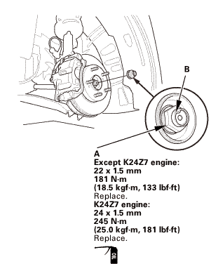 22x15mm15mm
| 4. | Lower Ball Joint Lower Arm Side - Reconnection |
|
|
|
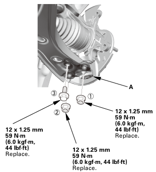 55(ini15mm(skg!m,12x125mm
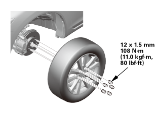
| 5. | Front Wheel |
|
|
|
||||||
 mmmln-mnomm
| 6. | Pre-Alignment Checks |
|
| 7. | Caster - Inspection |
|
|||||||||||||||||||||||||||||||||||||||||||||||
| 8. | Camber - Inspection |
|
||||||||||||||||||||||||||||||||||||||||||||||||||||||||||||||||||||||||||||||||||||||
| 9. | Front Toe - Inspection |
|
|||||||||||||||||||||||||
| 10. | Turning Angle - Inspection |
|
|
|
|||||||||||||||||||||||||||||||||||||||||||||||||||||||||||||||||||||||||||||||||||||||||
|
|
|
|||||||||||||||||||||||||||||||||||||||||||||||||||||||||
 Ball Joint Boot Inspection
1.
Vehicle Lift
1.
Raise the vehicle on a lift, and make sure it is securely supported.
2. ...
 Steering Tie-Rod End Ball Joint Boot Replacement
5111A8 LEFT
5111A9 RIGHT
5111B0 BOTH
1.
Vehicle Lift
1.
Raise the vehicle on a lift, and make sure it is securely sup ...
See also:
Honda Civic Service Manual. Trunk Lid Opener/Fuel Fill Door Opener Removal and Installation
849110
Removal
1.
Front Door Sill Trim - 4-Door
1.
Remove the cap (A) from the front door sill trim (B).
...
