Honda Civic Service Manual: EPS Motor Removal and Installation
511102

|
NOTE: Do not allow dust, dirt, or other foreign materials to enter the steering gearbox. |
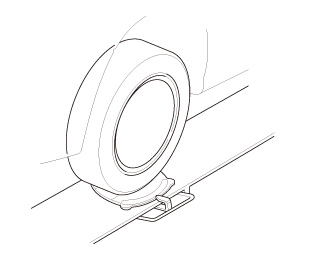
| 1. | Vehicle Lift |
|
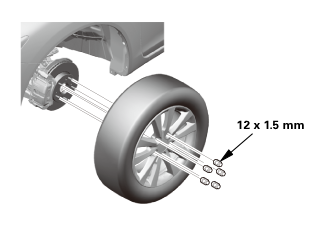
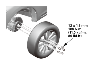
| 2. | Front Wheel |
|
|
|
| 3. | Steering Joint Cover |
|
|
|
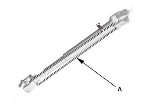
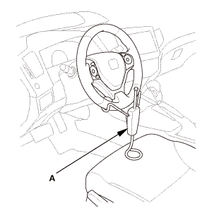
| 4. | Steering Column Lower Slide Shaft - Hold |
|
|
|
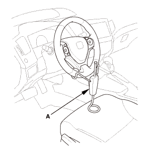
| 5. | Steering Wheel Hold |
|
|
|
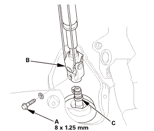
| 6. | Steering Joint Bolt - Loosen |
|
|
|
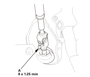
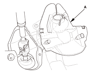
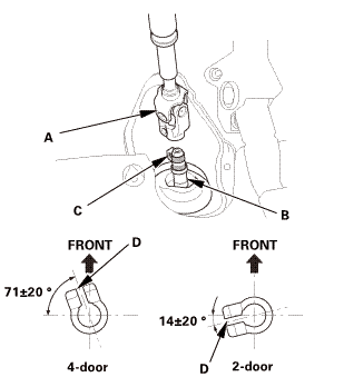
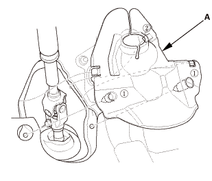
| 7. | Steering Joint - Disconnection |
|
|
|
||||||||||||||||||||

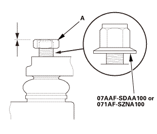
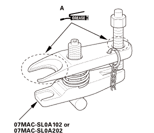
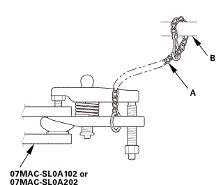
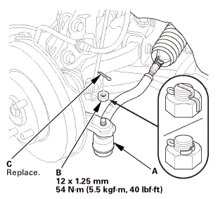
| 8. | Ball Joint - Removal |
|
|
Always use a ball joint remover to disconnect a ball joint. Do not strike the housing or any other part of the ball joint connection to disconnect it.
|
||||||

|
|
|
 ov
ov|
|
|
||||||||||||||||||||||||||||||||
 wmae-sldaidz
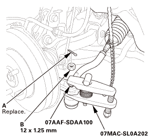
| 9. | Tie-Rod End Ball Joint - Disconnection, Both Side |
|
|
|
||||||||||||
 n7aaf-sdaainnmm
| 10. | Engine Undercover |
|
|
|

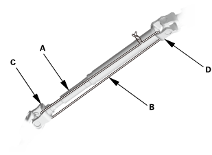
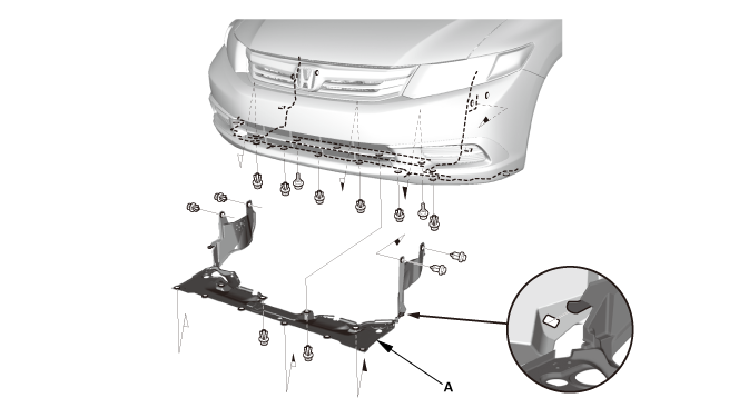
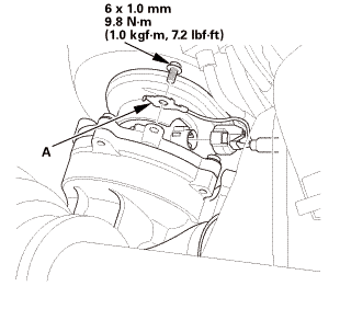
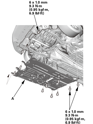
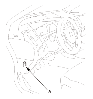
| 11. | Splash Shield |
|
1. |
Remove the splash shield (A). |
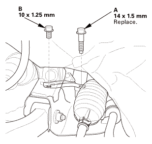
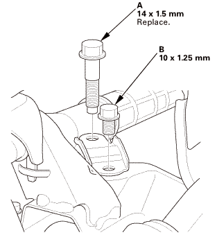
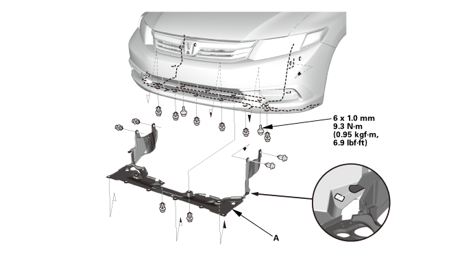
| 12. | Power Steering Gearbox Peripheral Assembly |
|
|
|
|
Driver’s side
Passenger’s side
|
|
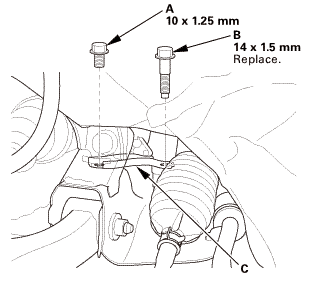
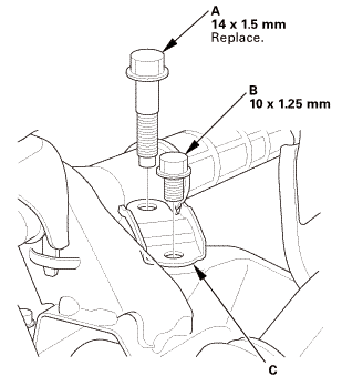
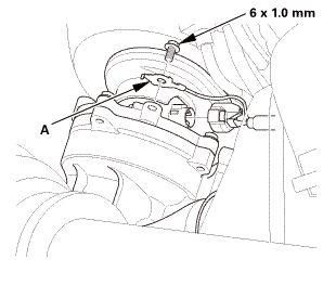
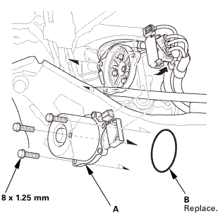
| 13. | EPS Motor |
|
|
|
 ixusmm
|
NOTE: Do not allow dust, dirt, or other foreign materials to enter the steering gearbox. |
| 1. | EPS Motor |
|
|
|
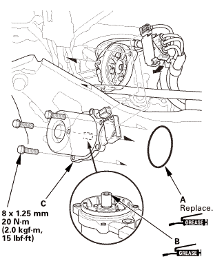
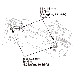
| 2. | Power Steering Gearbox Peripheral Assembly |
|
|
|
|
|
|
|
|
|
 m,iminmm
|
|
|
 mmm:im
| 3. | Splash Shield |
|
1. |
Install the splash shield (A). |
| 4. | Engine Undercover |
|
|
|
| 5. | Tie-Rod End Ball Joint - Connection, Both Side |
|
|
|
|||||||||||||||
| 6. | Steering Column Lower Slide Shaft - Release |
|
|
|
| 7. | Steering Wheel Release |
|
|
|
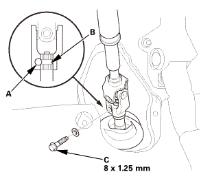
| 8. | Steering Joint - Reconnection |
|
|
|
||||||||||||||||||||
|
|
|
| 9. | Steering Joint Bolt - Tighten |
|
|
|
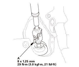 mm:.o21
| 10. | Steering Joint Cover |
|
|
|
| 11. | Front Wheel |
|
|
|
||||||
 mmmln-mnomm
| 12. | Steering Gearbox - After Install Symptom Check |
|
|||||||||||||||||
| 13. | Steering After Install - Check |
|
|||||||||||||||||||
| 14. | Pre-Alignment Checks |
|
| 15. | Caster - Inspection |
|
|||||||||||||||||||||||||||||||||||||||||||||||
| 16. | Camber - Inspection |
|
||||||||||||||||||||||||||||||||||||||||||||||||||||||||||||||||||||||||||||||||||||||
| 17. | Front Toe - Inspection |
|
|||||||||||||||||||||||||
| 18. | Turning Angle - Inspection |
|
|
|
|||||||||||||||||||||||||||||||||||||||||||||||||||||||||||||||||||||||||||||||||||||||||
|
|
|
|||||||||||||||||||||||||||||||||||||||||||||||||||||||||
| 19. | HDS DLC - Connection |
|
|
|
| 20. | EPS Torque Sensor Neutral Position - Memorizing |
|
||||||||||||||||
| 21. | VSA Sensor Neutral Position - Memorization |
|
||||||||||
| 22. | Steering Angle Sensor Neutral Position - Clear |
|
|||||||
 EPS Control Unit Removal and Installation
513130
Removal
1.
Front Door Sill Trim - 2-Door
1.
Remove the front door sill trim (A).
...
 Power Steering Assist Check
Check
1.
Power Steering Assist Check
NOTE: This test should be done with original equipment tires and wheels
at the correct tire pressure.
...
See also:
Honda Civic Owners Manual. What to Do After the Engine Starts
Once your vehicle's engine has started, remove the jumper cables in the
following
order.
Disconnect the jumper cable from your vehicle's ground.
Disconnect the other end of the jumper cable from the booster
battery -
terminal.
Disconnect the jumper cable from your v ...
