Honda Civic Service Manual: Engine Removal and Installation (R18Z1 (A/T, M/T))
11010A

| 1. | Vehicle Lift |
|
| 2. | Wide - Hood Open Position |
|
|
|
| 3. | Fuel Filler Cap |
|
| 4. | HDS DLC - Connection |
|
|
|
| 5. | Fuel Pump Off |
|
||||||||||||||||||||||||

| 6. | Battery Terminal - Disconnection |
|
|
|
|||||||||||||||||||||||||||
| 7. | Fuel Pressure - Relieving |
|
|
|
|
|
|
|
|
|
|||||||||||||||||||||||||
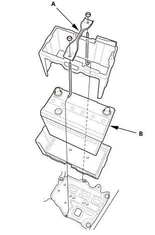
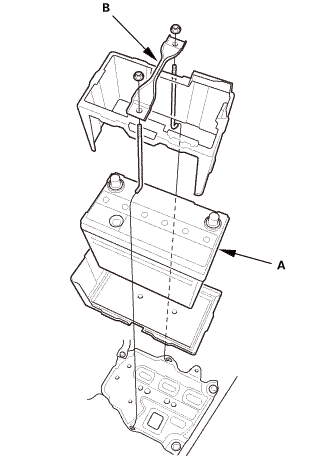
| 8. | Battery |
|
|
|
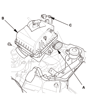
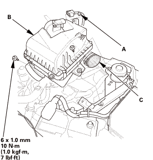
| 9. | Intake Air Pipe |
|
|
|
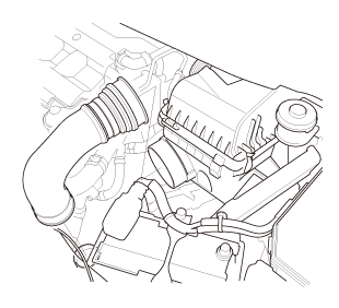
| 10. | Air Cleaner |
|
|
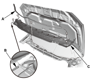
|
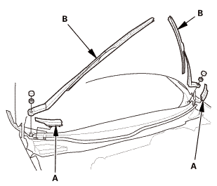
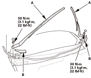
| 11. | Wiper Arm Assembly |
|
|
|
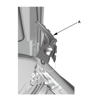
| 12. | Both Side Cowl Covers |
|
|
|
| 13. | Center Cowl Cover |
|
|
|

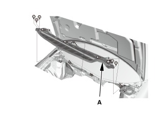
| 14. | Under Cowl Panel |
|
|
|
| 15. | Engine Cover |
|
|
|
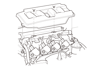
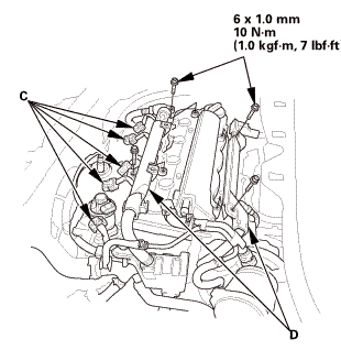
| 16. | Intake Manifold Peripheral Assembly |
|
|
|
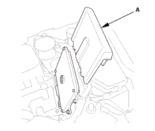
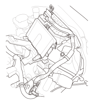
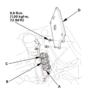
| 17. | ECM/PCM |
|
|
|
|
|
|
|||||||||
| 18. | Air Cleaner Bracket |
|
|
|
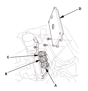
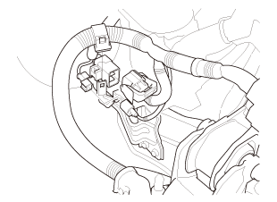
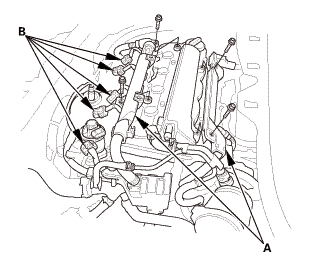
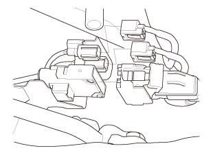
| 19. | Engine Wire Harness - Disconnection |
|
|
|
|
|
|
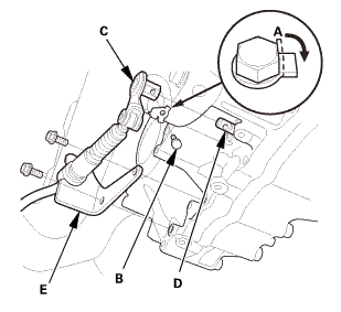
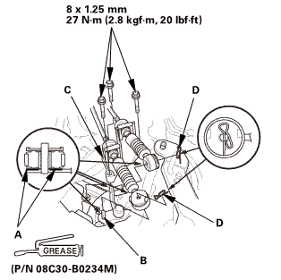
| 20. | Shift Cable Bracket |
|
|
|
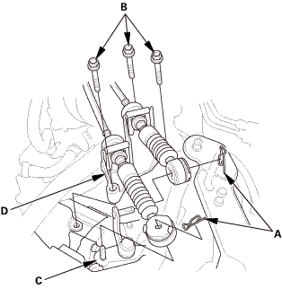
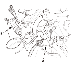
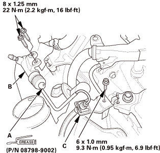
| 21. | Slave Cylinder |
|
|
|
|||||||||||||||||||||||
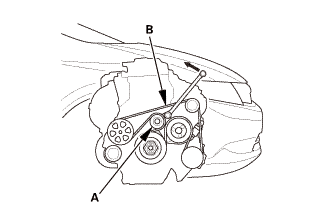
| 22. | Drive Belt |
|
|
|
| 23. | Radiator Cap |
|
| 24. | Raise The Vehicle On The Lift |
|
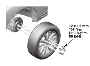
| 25. | Front Wheel |
|
|
|
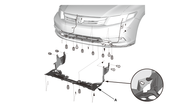
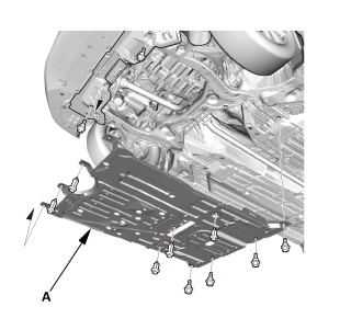
| 26. | Splash Shield |
|
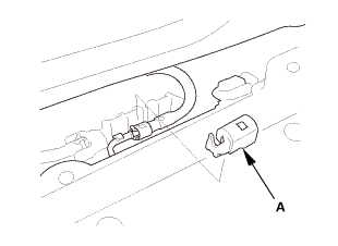
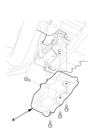
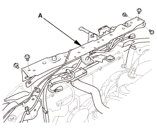
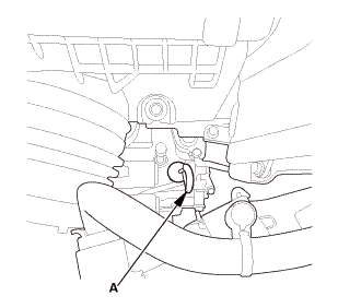
1. |
Remove the splash shield (A). |
| 27. | Engine Undercover |
|
|
|
| 28. | Radiator Coolant - Replacement |
|
|
|
| 29. | Cylinder Block Coolant - Drain (Except K24Z7 engine ) |
|
|
|
 1.5mmn-mm
| 30. | Engine Oil - Replacement |
|
|
|
| 31. | MTF Replacement (M/T) |
|
|
|
| 32. | ATF Replacement (A/T) |
|
|
|
| 33. | Exhaust Pipe A (Except CVT) |
|
|
|
| 34. | Shift Cable Cover (A/T) |
|
|
|
| 35. | Shift Cable A/T Side - Disconnection |
|
|
|
|||||||||||||||
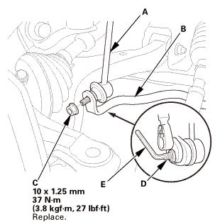
| 36. | Front Stabilizer Ball Joint - Disconnection, Both Lower Arm Side |
|
|
|
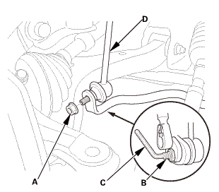
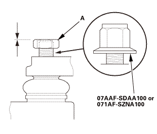
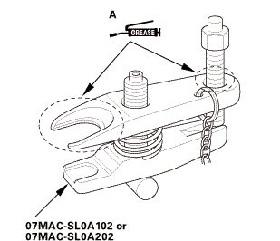
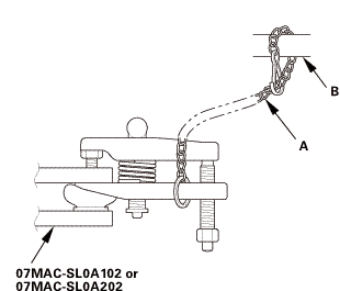
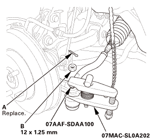
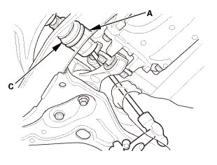
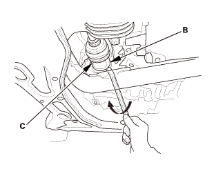
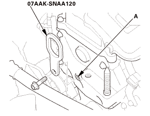
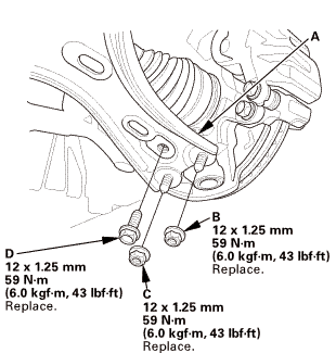
| 37. | Ball Joint - Removal |
|
|
Always use a ball joint remover to disconnect a ball joint. Do not strike the housing or any other part of the ball joint connection to disconnect it.
|
||||||

|
|
|
 ov
ov|
|
|
||||||||||||||||||||||||||||||||
 wmae-sldaidz
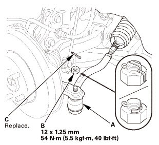
| 38. | Tie-Rod End Ball Joint - Disconnection, Both Side |
|
|
|
||||||||||||
 n7aaf-sdaainnmm
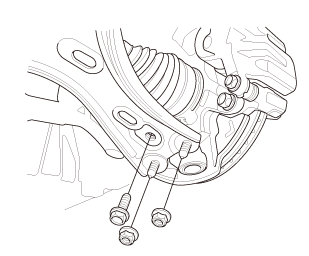
| 39. | Lower Arm Joint - Disconnection, Both Knuckle Side |
|
|
|
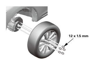
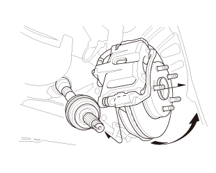
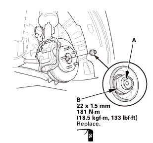
| 40. | Front Driveshaft Spindle Nut Both |
|
|
|
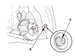
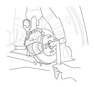
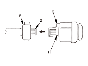
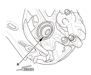
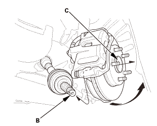
| 41. | Front Driveshaft Both Outboard Side - Disconnection |
|
|
|
|
|
|
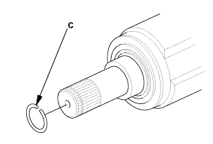
| 42. | Driveshaft Front Both - Disconnection Inboard Side |
|
|
|
||||||||||||||||||||
|
With intermediate shaft
Without intermediate shaft
With intermediate shaft
Without intermediate shaft
|
|
|||||||||||||||||||||||||||||
| 43. | Lower The Vehicle On The Lift |
|
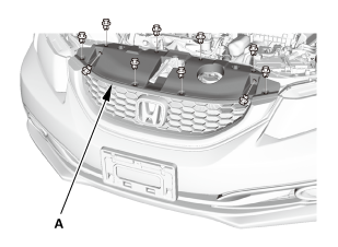
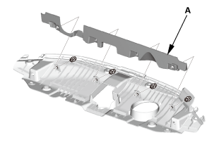
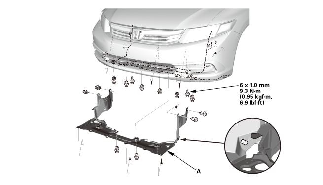
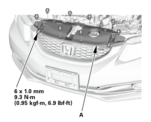
| 44. | Front Grille Cover |
|
|
|
|
|
|
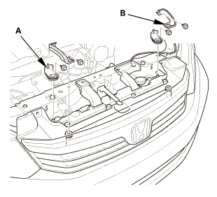
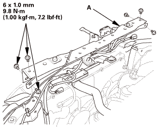
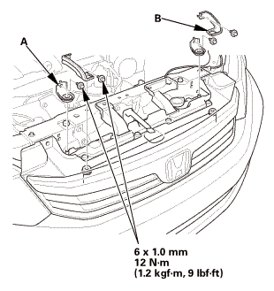
| 45. | Radiator Mounting Bracket, Upper Both |
|
|
|
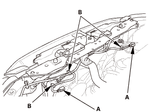
| 46. | Bulkhead - Removal |
|
|
|
|
|
|
| 47. | Radiator Assembly |
|
|
|
|
|
|
|
|
|
| 48. | A/C ompressor Assembly - Move |
|
|
|
||||||||||||
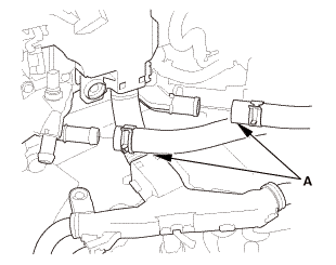
| 49. | Heater Hose - Disconnection, Engine Side |
|
|
|
| 50. | Bulkhead - Temporary Install |
|
|
|
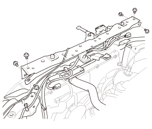
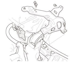
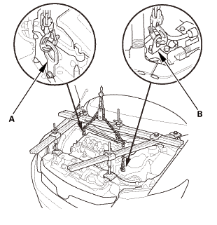
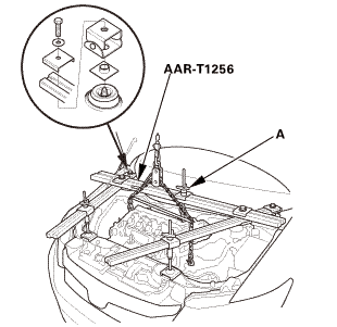
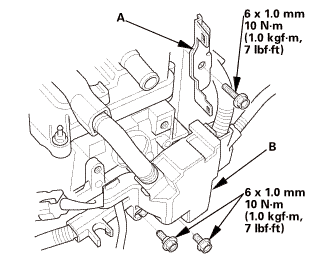
| 51. | Engine Support Hanger Peripheral Assembly |
|
|
|
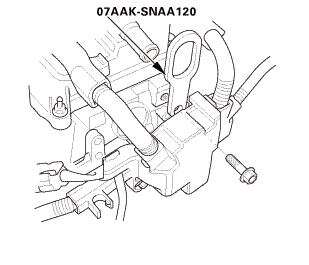
| 52. | Engine Support Hanger |
|
|
|
|
|
|
||||||||||||
| 53. | Steering Joint Cover |
|
|
|
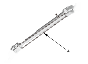
| 54. | Steering Column Lower Slide Shaft - Hold |
|
|
|
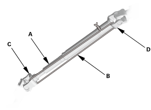
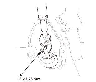
| 55. | Steering Joint Bolt - Loosen |
|
|
|
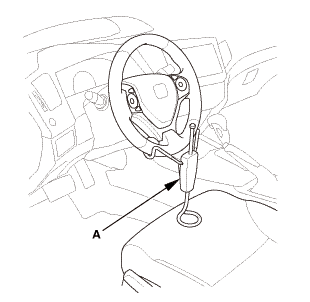
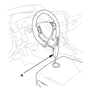
| 56. | Steering Wheel Hold |
|
|
|
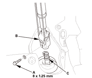
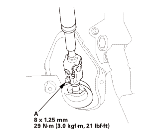
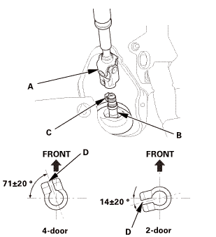
| 57. | Steering Joint - Disconnection |
|
|
|
||||||||||||||||||||
| 58. | Raise The Vehicle On The Lift |
|
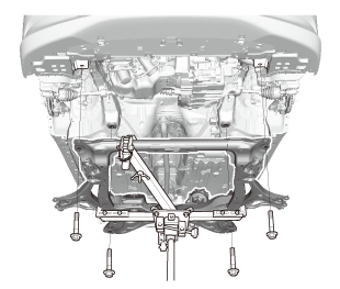
| 59. | Lower Torque Rod - Disconnection |
|
|
|
| 60. | Subframe Support |
|
|
|
| 61. | Front Subframe Assembly |
|
|
|
|
|
|
|
|
|
| 62. | Lower The Vehicle On The Lift |
|
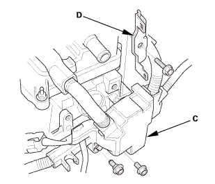
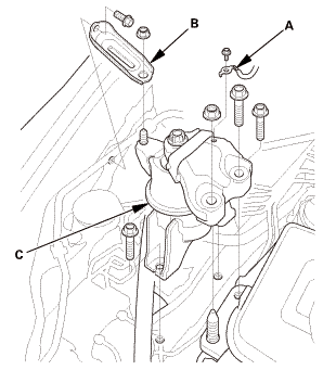
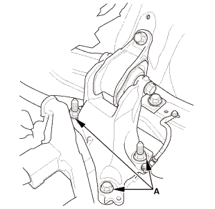
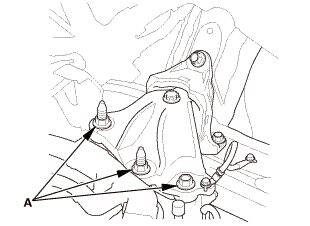
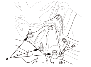
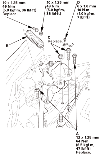
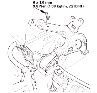
| 63. | Mounting Bracket, Engine Side |
|
|
|
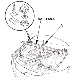
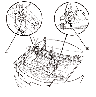
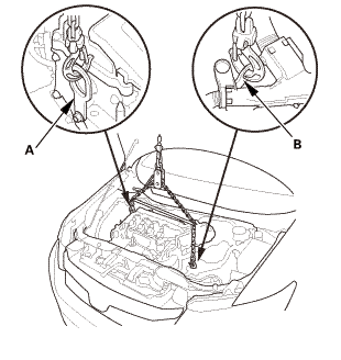
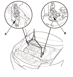
| 64. | Chain Hoist |
|
|
|
|
M/T
A/T
|
|
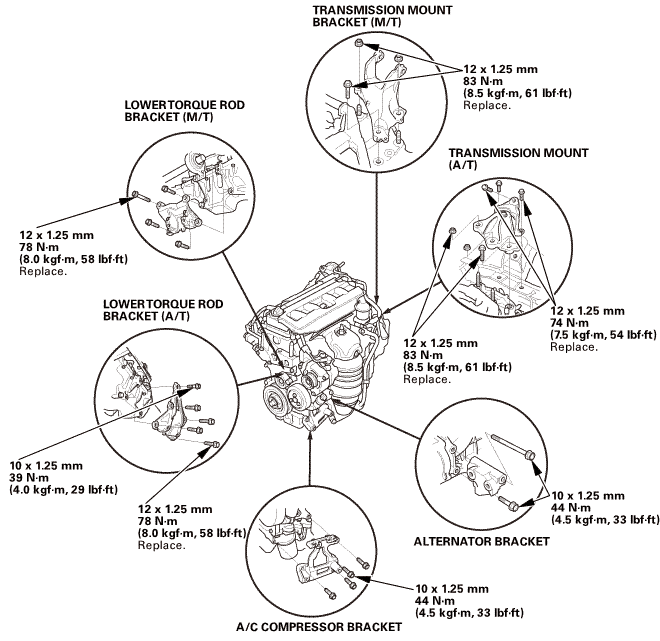
| 65. | Transmission Mount (M/T) |
|
M/T
|
|
| 66. | Transmission Mount (A/T) |
|
A/T
|
|
| 67. | Engine Removal |
|

| 1. | Engine Installation |
|
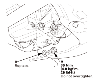
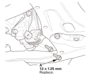
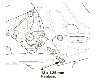
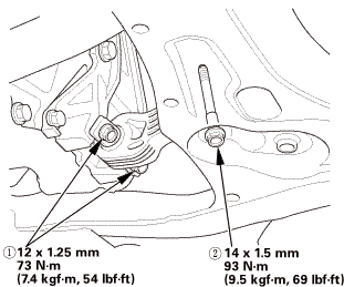
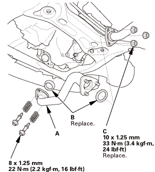
1. |
Install the lower torque rod bracket, and tighten the new bolts to the specified torque. |
 maum12125mmm...(m/i1mmsmlsslnumumin12125mmm...nonli/hi)m...1.15m...m...mmaic
| 2. | Chain Hoist |
|
M/T
A/T
|
|
|||||||||
| 3. | Engine Support Hanger |
|
|
|
|
|
|
||||||||||||
| 4. | Transmission Mount (M/T) |
|
|
|
| 5. | Transmission Mount (A/T) |
|
|
|
| 6. | Chain Hoist |
|
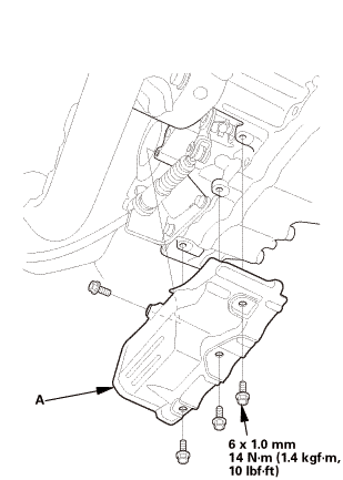
| 7. | Mounting Bracket, Engine Side |
|
|
|
 125mmnminm.:125mm
| 8. | Raise The Vehicle On The Lift |
|
| 9. | Subframe Support |
|
|
|
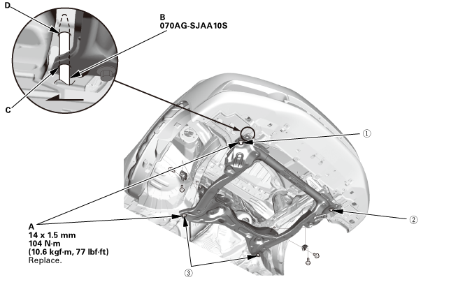
| 10. | Front Subframe Assembly |
|
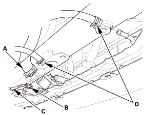
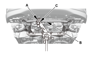
1. |
Loosely install the new front subframe mounting bolts (A). |
 o7oagsjaaosn-m77lm41!
|
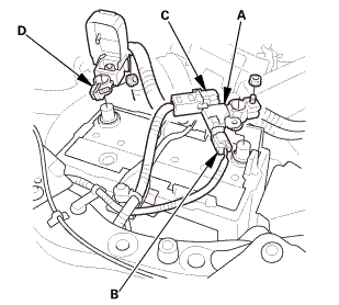
2. |
Insert the subframe alignment pin (B) through the positioning hole (C) on the right front subframe, and into the positioning hole (D) on the body, then loosely tighten the subframe right front mounting bolt. |
|
3. |
Insert the subframe alignment pin through the positioning slot on the left front subframe, and into the positioning hole on the body, then loosely tighten the subframe left front mounting bolt. |
|
4. |
Tighten the subframe mounting bolts to the specified torque values starting with the right front subframe mounting bolt. Use the subframe alignment pin when tightening the front side subframe mounting bolts. |
|
5. |
Check all of the subframe mounting bolts, and retighten if necessary. |
|
|
NOTE: Tighten the bolts in the sequence shown. |
||
|
6. |
Remove the transmission jack and the subframe adapter. |
|
|
|
|
|
|
| 11. | Lower Torque Rod - Connection |
|
|
|
| 12. | Lower The Vehicle On The Lift |
|
| 13. | Engine Support Hanger |
|
|
|
| 14. | Engine Support Hanger Peripheral Assembly |
|
|
|
| 15. | Steering Column Lower Slide Shaft - Release |
|
|
|
| 16. | Steering Wheel Release |
|
|
|
| 17. | Steering Joint Bolt - Tighten |
|
|
|
 mm:.o21
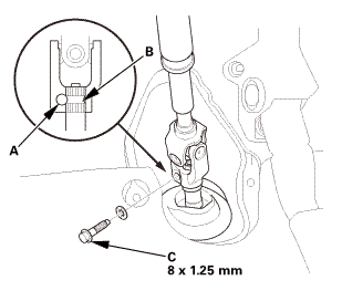
| 18. | Steering Joint - Reconnection |
|
|
|
||||||||||||||||||||
|
|
|
| 19. | Steering Joint Cover |
|
|
|
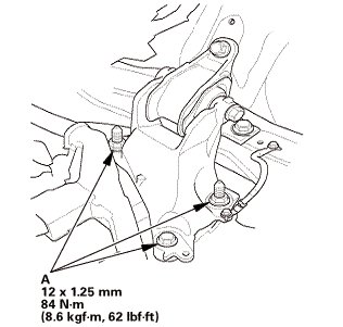
| 20. | Side Engine Mount - Tighten |
|
|
|
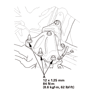
| 21. | Transmission Mount Bracket Mounting Bolt - Tighten (M/T) |
|
|
|
| 22. | Transmission Mount Bracket Mounting Bolt - Tighten (A/T) |
|
|
|
 -2l25mmkvf-m,
| 23. | Raise The Vehicle On The Lift |
|
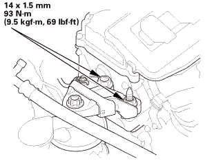
| 24. | Lower Torque Rod - Tighten |
|
|
|
 7:inmmss
| 25. | Driveshaft Front Both - Reconnection Inboard Side |
|
|
|
||||||||||||||||||
|
With intermediate shaft
With intermediate shaft
With intermediate shaft
|
|
|||||||||||||||||||||
|
Without intermediate shaft
Without intermediate shaft
|
|
||||||||||||||||||
| 26. | Front Driveshaft Both Outboard Side - Reconnection |
|
|
|
|||||||||
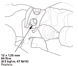
| 27. | Front Driveshaft Spindle Nut Both |
|
|
|
| 28. | Lower Arm Joint - Reconnection, Both Knuckle Side |
|
|
|
 mm
mm| 29. | Tie-Rod End Ball Joint - Connection, Both Side |
|
|
|
|||||||||||||||
| 30. | Front Stabilizer Ball Joint - Reconnection, Both Lower Arm Side |
|
|
|
 27m.27
| 31. | Shift Cable A/T Side - Reconnection |
|
|
|
| 32. | Shift Cable Cover (A/T) |
|
|
|
 i.mmn-mid
| 33. | Exhaust Pipe A (Except CVT) |
|
|
|
 inmm125mm22i21
| 34. | Lower The Vehicle On The Lift |
|
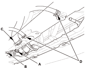
| 35. | Heater Hose - Reconnection, Engine Side |
|
|
|
| 36. | Bulkhead - Temporary Remove |
|
|
|
| 37. | A/C Compressor Assembly - Move |
|
|
|
| 38. | Drive Belt |
|
|
|
| 39. | Radiator Assembly |
|
|
|
|
|
|
|
|
|
| 40. | Engine Undercover |
|
|
|
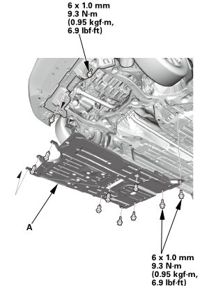
| 41. | Splash Shield |
|
1. |
Install the splash shield (A). |
| 42. | Bulkhead - Installation |
|
|
|
|
|
|

| 43. | Radiator Mounting Bracket, Upper Both |
|
|
|
| 44. | Front Grille Cover |
|
|
|
|
|
|
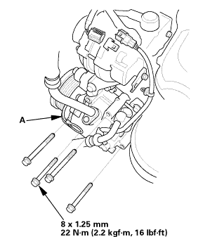
| 45. | Slave Cylinder |
|
|
|
||||||||||||
 .25mmm.is
| 46. | Shift Cable Bracket |
|
|
|
|||||||||||||||
| 47. | Air Cleaner Bracket |
|
|
|
 in
in| 48. | ECM/PCM |
|
|
|
|||||||||
|
|
|
| 49. | Engine Wire Harness - Reconnection |
|
|
|
|
|
|
| 50. | Intake Manifold Peripheral Assembly |
|
|
|
| 51. | Engine Cover |
|
|
|
| 52. | Under Cowl Panel |
|
|
|
 22mm)2222
| 53. | Center Cowl Cover |
|
|
|
| 54. | Both Side Cowl Covers |
|
|
|
| 55. | Wiper Arm Assembly |
|
|
|
 1.122
1.122| 56. | Air Cleaner |
|
|
|
| 57. | Intake Air Pipe |
|
|
|
| 58. | Front Wheel |
|
|
|
||||||
 mmmln-mnomm
| 59. | Battery |
|
|
|
||||||
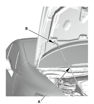
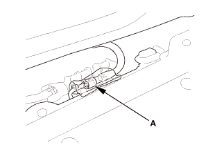
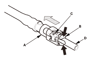
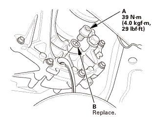
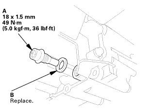
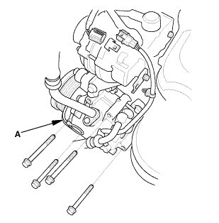
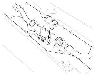
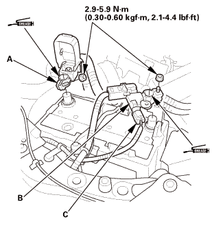
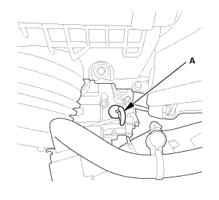
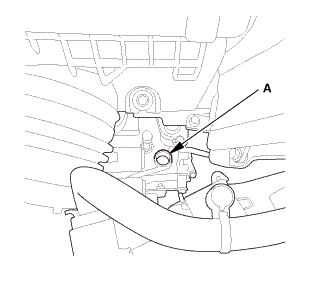
| 60. | Injector Base Fuel Feed Hose - Reconnection |
|
|
|
| 61. | Battery Terminal - Reconnection |
|
|
|
|||||||||||||||||||
| 62. | HDS DLC - Connection |
|
|
|

| 63. | Fuel Pump On |
|
||||||||||
| 64. | Fuel Filler Cap |
|
| 65. | Fuel Line Leak Check |
|
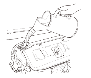
| 66. | Engine Oil - Replacement |
|
|
|
|||||||||||||||||||||||||||||
| 67. | MTF Replacement (M/T) |
|
|
|
||||||||||||||||||||||||||
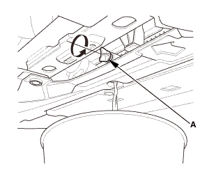
| 68. | ATF Replacement (A/T) |
|
|
|
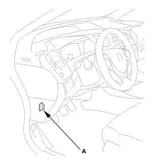
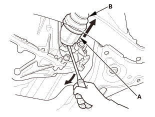
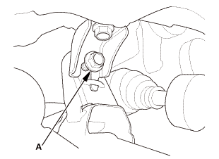
|
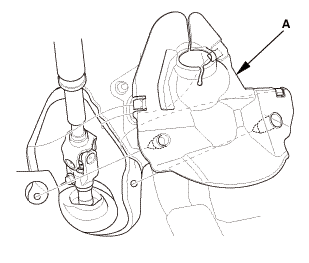
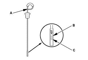
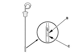
2. |
Refill the transmission with the recommended fluid through the dipstick hole (A) to bring the fluid level between the upper mark and the lower mark of the dipstick. Always use Honda automatic transmission fluid (ATF) ATF DW-1. Using a non-Honda ATF can affect shift quality. |
|||||||
|
Automatic Transmission Fluid Capacity:
|
||||||||
|
|
|
| 69. | Manual Transmission After Install - Check |
|
| 70. | AT Transmission After Install - Check |
|
| 71. | Radiator Coolant - Replacement |
|
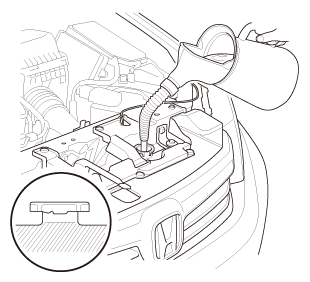
1. |
Follow the chart and pour coolant into the radiator up to the base of the filler neck. |
|||||||||||||||||||||||||||||||||||||
|
NOTE: |
||||||||||||||||||||||||||||||||||||||
|
||||||||||||||||||||||||||||||||||||||
|
||||||||||||||||||||||||||||||||||||||
|
*: When you want to winterize the coolant with the minimum amount of coolant change but the current coolant concentration in the vehicle is unknown, you must drain all coolant from the cooling system. |
||||||||||||||||||||||||||||||||||||||
|
||||||||||||||||||||||||||||||||||||||
|
||||||||||||||||||||||||||||||||||||||
|
||||||||||||||||||||||||||||||||||||||
|
||||||||||||||||||||||||||||||||||||||
| 72. | Engine Installation After Install - Check (A/T) |
|
| 73. | Warm Up The Engine Wait Few Minutes |
|
| 74. | ATF Level Check |
|
|
|
| 75. | Idle Speed - Inspection |
|
||||||||||||||||||||||||||||
| 76. | CKP Pattern Clear/CKP Pattern Learn |
|
| 77. | Ignition Timing - Inspection |
|
|
|
|
|
|
||||||||||||||||
| 78. | Pre-Alignment Checks |
|
| 79. | Caster - Inspection |
|
|||||||||||||||||||||||||||||||||||||||||||||||
| 80. | Camber - Inspection |
|
||||||||||||||||||||||||||||||||||||||||||||||||||||||||||||||||||||||||||||||||||||||
| 81. | Front Toe - Inspection |
|
|||||||||||||||||||||||||
| 82. | Turning Angle - Inspection |
|
|
|
|||||||||||||||||||||||||||||||||||||||||||||||||||||||||||||||||||||||||||||||||||||||||
|
|
|
|||||||||||||||||||||||||||||||||||||||||||||||||||||||||
| 83. | VSA Sensor Neutral Position - Memorization |
|
||||||||||
| 84. | Steering Angle Sensor Neutral Position - Clear |
|
|||||||
| 85. | Maintenance Minder Reset |
|
 ECM/PCM Removal and Installation (Except K24Z7 and R18Z1 (CVT))
1211K3
1.
HDS DLC - Connection
NOTE: For specific operations, refer to the user's manual that
came with the Honda Diagnos ...
 Exhaust Pipe and Muffler Removal and Installation (Except K24Z7 and R18Z1 (CVT))
NOTE: Use new gaskets, new self-locking nuts, and new bolts when reassembling.
1.
Exhaust Pipe and Muffler
nommn-msmsmusm/rexmmmmi25ummn)
...
See also:
Honda Civic Owners Manual. Important Safety Precautions
Always wear your seat belt
A seat belt is your best protection in all types of collisions. Airbags are
designed to
supplement seat belts, not replace them. So even though your vehicle is equipped
with airbags, make sure you and your passengers always wear your seat belts, and
wear them properl ...
