Honda Civic Service Manual: Engine Oil Pump Removal and Installation (Except K24Z7)
111150

| 1. |
Battery Terminal - Disconnection |
|
|
|
1.
|
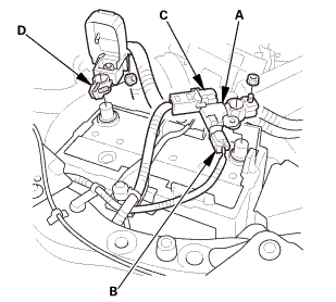
Make sure the ignition switch is in LOCK (0), or the vehicle
ignition in the OFF mode.
|
|
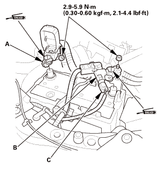
2.
|
Disconnect and isolate the negative cable with the battery sensor
(A) from the battery.
|
|
NOTE:
|
|

|
Always disconnect the negative side first.
|
|
|
|
To protect the battery sensor connector (B) from
damage, do not hold it when removing the negative
terminal.
|
|
|
|
Do not disconnect the battery sensor from the
negative terminal (C).
|
|
|
|
3.
|
Disconnect the positive cable (D) from the battery.
|
|
|
|
|
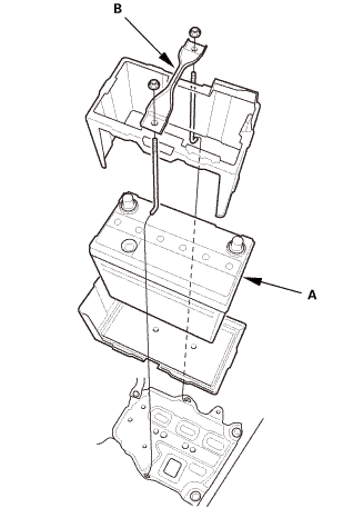
1.
|
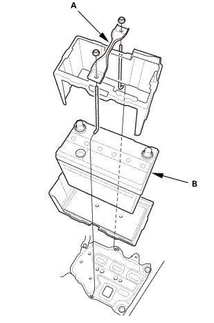
Remove the battery setting plate (A) and the battery (B).
|
|
|
|
1.
|
Raise the vehicle on a lift, and make sure it is securely supported.
|
|
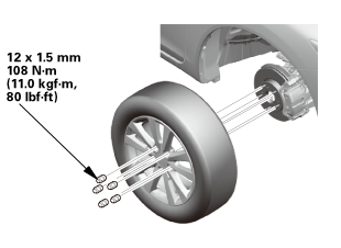
| 4. |
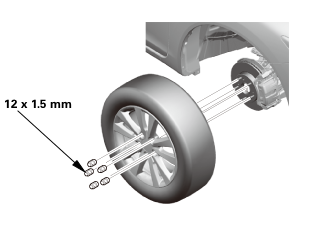
Tire and Wheel-Removal, Front Right |
|
 12x1mm 12x1mm
|
|
1.
|
Remove the right front wheel.
|
|
|
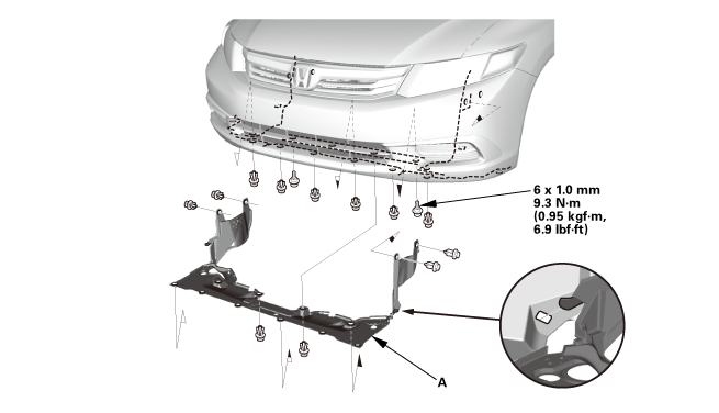
1.
|
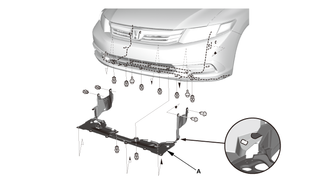
Remove the splash shield (A).
|
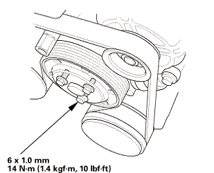
| 6. |
Water Pump Pulley Mounting Bolt - Loosen |
|
|
|
1.
|
Loosen the water pump pulley mounting bolts.
|
|
|
|
|
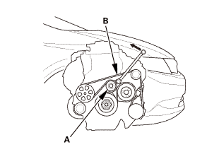
1.
|
Move the auto-tensioner (A) counterclockwise to relieve tension
from the drive belt (B).
|
|
2.
|
Remove the drive belt.
|
|
|
|
|
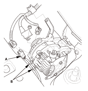
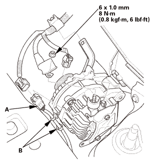
1.
|
Disconnect the connector and the cable.
|
|
2.
|
Remove the harness connector (A) and the harness clamps (B).
|
|
|
|
|
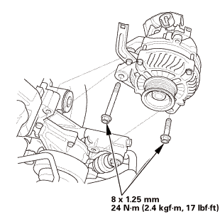
3.
|
Remove the alternator.
|
|
|
|
|
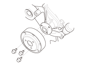
1.
|
Remove the water pump pulley.
|
|
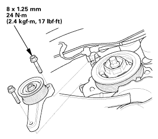
| 10. |
Auto Tensioner Assembly |
|
|
|
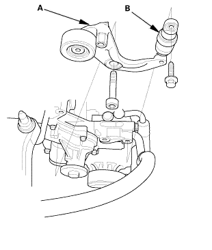
1.
|
Remove the drive belt auto-tensioner (A).
|
|
2.
|
Check for oil leaks from the drive belt auto-tensioner damper
(B) and check for damage to the damper rubber.
|
|
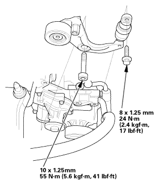
| 11. |
Idler Pulley Base Assembly |
|
|
|
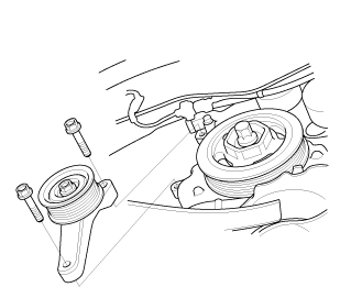
1.
|
Remove the idler pulley base.
|
|
|
|
|
1.
|
Remove the engine cover.
|
|
| 13. |
Cylinder Head Cover Peripheral Assembly |
|
|
|
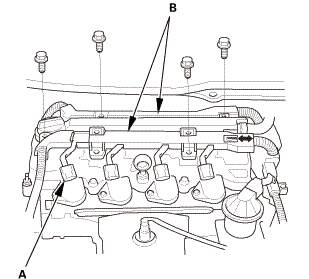
1.
|
Disconnect the connecters (A).
|
|
2.
|
Remove the harness holders (B).
|
|
| 14. |
Cylinder Head Cover and/or Packing |
|
|
|
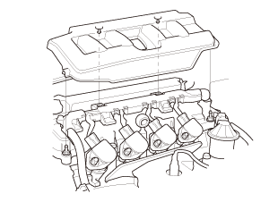
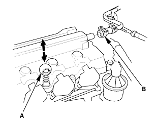
1.
|
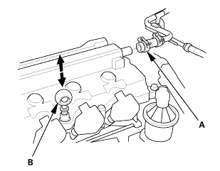
Remove the dipstick (A).
|
|
2.
|
Disconnect the breather hose (B).
|
|
|
|
|
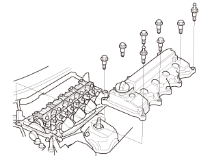
3.
|
Remove the cylinder head cover.
|
|
|
 [av [av
|
|
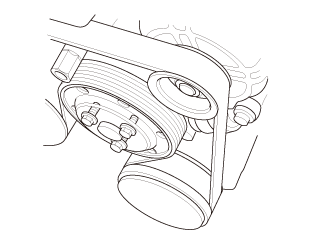
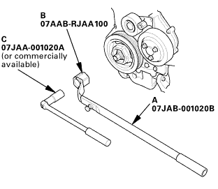
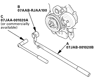
1.
|
Hold the pulley with the holder handle (A) and the crankshaft
pulley holder (B).
|
|
2.
|
Remove the bolt with a socket, 19 mm (C) and a breaker bar.
|
|
3.
|
Remove the crankshaft pulley.
|
|
| 16. |
Engine Jack Support (State Of A Low Vehicle) |
|
|
1.
|
Lift and support the engine with a jack and a wood block under
the oil pan.
|
|
| 17. |
Mounting Bracket, Engine Side |
|
|
|
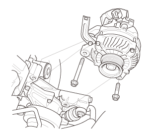
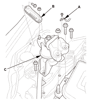
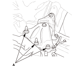
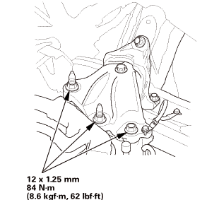
1.
|
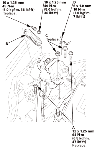
Remove the ground cable (A), the side engine mount bracket (B),
and the side engine mount (C).
|
|
| 18. |
Engine Oil Pump Assembly |
|
|
|
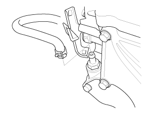
1.
|
Disconnect the PCV hose.
|
|

| 1. |
Engine Oil Pump Assembly |
|
|
|
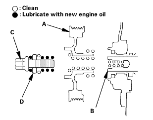
1.
|
Check the oil pump oil seal for damage. If the oil seal is damaged,
replace the oil seal.
|
|
2.
|
Remove all of the old liquid gasket from the oil pump mating
surfaces, the bolts, and the bolt holes.
|
|
3.
|
Clean and dry the oil pump mating surfaces.
|
|
4.
|
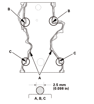
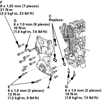
Apply liquid gasket (P/N 08718-0004 or 08718-0009) to the engine
block mating surface of the oil pump, and to the inside edge of
the threaded bolt holes. Install the component within 5 minutes
of applying the liquid gasket.
|
|
NOTE:
|
|
|
Apply a 2.5 mm (0.098 in) diameter bead of liquid
gasket along the broken line (A), (B), and (C).
|
|
|
|
If too much time has passed after applying the
liquid gasket, remove the old liquid gasket and
residue, then reapply new liquid gasket.
|
|
|
|
|
|
|
5.
|
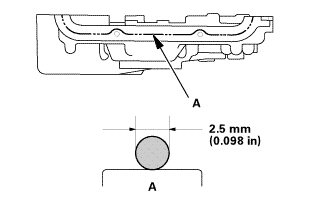
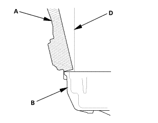
Apply liquid gasket (P/N 08718-0004 or 08718-0009) to the oil
pan mating surface of the oil pump, and to the inside edge of the
threaded bolt holes. Install the component within 5 minutes of applying
the liquid gasket.
|
|
|
Apply a 2.5 mm (0.098 in) diameter bead of liquid
gasket along the broken line (A).
|
|
|
|
If too much time has passed after applying the
liquid gasket, remove the old liquid gasket and
residue, then reapply new liquid gasket.
|
|
|
|
|
 25mm(7(32k1n1omm12 25mm(7(32k1n1omm12
|
|
6.
|
Set the edge of the oil pump (A) on the edge of the oil pan (B)
with new O-rings (C).
|
|
7.
|
Install the oil pump on the engine block (D).
|
|
8.
|
Loosely install the dowel bolts (E), then tighten the 8mmbolts
(F), the 6 mm bolts (G) and the dowel bolts.
|
|
9.
|
Wipe off the excess liquid gasket on the oil pan and oil pump
mating surface.
|
|
NOTE:
|
|
|
When installing the oil pump, do not slide the
bottom surface onto the oil pan mounting surface.
|
|
|
|
Wait at least 30 minutes before filling the engine
with oil.
|
|
|
|
Do not run the engine within 3 hours after installing
the oil pump.
|
|
|
|
| 2. |
Mounting Bracket, Engine Side |
|
 125mmnminm.:125mm 125mmnminm.:125mm
|
|
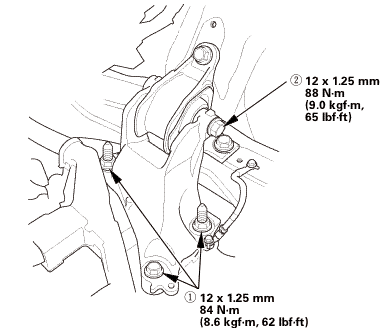
1.
|
Install the new side engine mount mounting bolts (A) and the
side engine mount bracket (B) using a nut and a new bolt, then loosely
install the new side engine mount bracket mounting bolts and nut
(C).
|
|
2.
|
Install the ground cable (D).
|
|
| 3. |
Engine Jack Support (State Of A Low Vehicle) |
|
|
1.
|
Remove the jack and the wood block.
|
|
| 4. |
Transmission Mount Bracket Mounting Bolt - Loosen |
|
M/T
A/T
|
|
1.
|
Loosen the transmission mount bracket mounting bolt and nuts
(A).
|
|
| 5. |
Lower Torque Rod - Loosen |
|
|
|
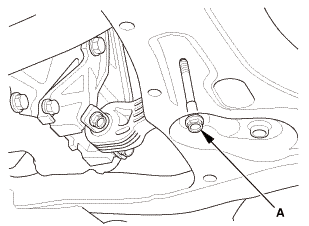
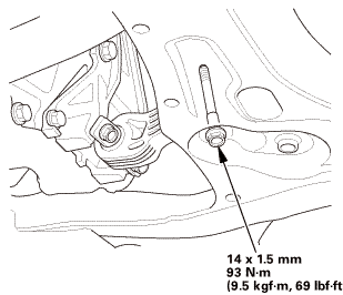
1.
|
Loosen the lower torque rod mounting bolt (A).
|
|
| 6. |
Side Engine Mount - Tighten |
|
 nxl.mm nxl.mm
|
|
1.
|
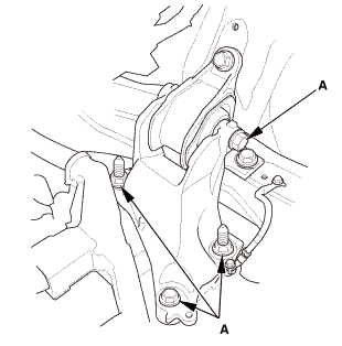
Tighten the side engine mount bracket mounting bolt and nut.
|
|
| 7. |
Transmission Mount Bracket Mounting Bolt - Tighten |
|
1.
|
Tighten the transmission mount bracket mounting bolt and nuts.
|
M/T
 i2mm
i2mm
A/T
 nz
nz
| 8. |
Lower Torque Rod Mounting Bolt - Tighten |
|
|
|
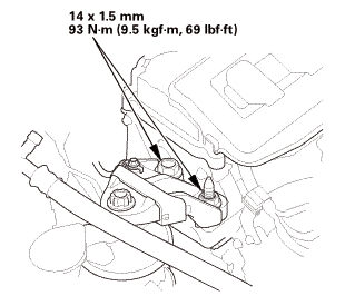
1.
|
Tighten the lower torque rod mounting bolt.
|
|
|
|
|
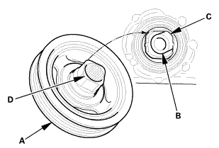
1.
|
Clean the crankshaft pulley (A), the crankshaft (B), the bolt
(C), and the washer (D).
|
|
2.
|
Lubricate with new engine oil as shown.
|
|
|
|
|
3.
|
Install the crankshaft pulley (A) onto the crankshaft (B) by
aligning the flat sides (C) of the pulley with the flat sides (D)
of the inner oil pump gear.
|
|
|
 o7jaanmo2oa o7jaanmo2oa
|
|
When a new crankshaft or a new pulley bolt is installed
|
|
4.
|
Hold the pulley with the holder handle (A) and crankshaft pulley
holder (B), torque the bolt to 180 N·m (18.4 kgf·m, 133 lbf·ft)
with a torque wrench and a socket (C), then remove the bolt.
|
|
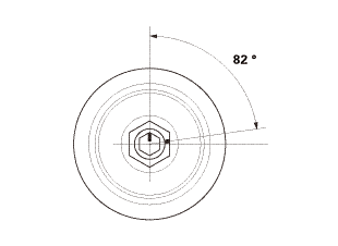
5.
|
Torque the bolt to 50 N·m (5.1 kgf·m, 37 lbf·ft) with a torque
wrench and a socket.
|
|
NOTE: Tighten the crankshaft pulley bolt. Do not use an impact
wrench.
|
|
6.
|
Tighten the bolt an additional 82 °.
|
|
|
o7jaanmo2oa
|
|
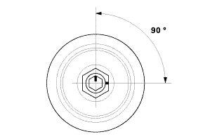
When the crankshaft or the pulley bolt is reused
|
|
7.
|
Hold the pulley with the holder handle (A) and crankshaft pulley
holder (B), then torque the bolt to 70 N·m (7.1 kgf·m, 52 lbf·ft)
with a torque wrench and a socket (C).
|
|
NOTE: Tighten the crankshaft pulley bolt. Do not use an impact
wrench.
|
|
8.
|
Tighten the bolt an additional 90 °.
|
|
| 10. |
Cylinder Head Cover and/or Packing |
|
|
|
1.
|
Thoroughly clean the head cover gasket and the groove.
|
|
NOTE: Check and, if necessary, replace the head cover gasket.
|
|
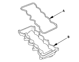
2.
|
Install the head cover gasket (A) in the groove of the cylinder
head cover (B).
|
|
3.
|
Make sure the head cover gasket is seated securely.
|
|
4.
|
Clean the head cover contacting surfaces with a shop towel.
|
|
|
|
|
5.
|
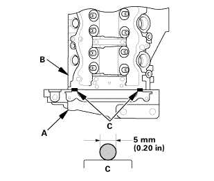
Remove the old liquid gasket from the top edge matting surfaces
of the oil pump (A) and cylinder head (B).
|
|
6.
|
Apply liquid gasket (P/N 08718-0004 or 08718-0009) to the chain
case contact areas. Install the component within 5 minutes of applying
the liquid gasket.
|
|
NOTE:
|
|
|
Apply a 5 mm (0.20 in) diameter bead of liquid
gasket to the mating surfaces (C).
|
|
|
|
If too much time has passed after applying the
liquid gasket, remove the old liquid gasket and
residue, then reapply new liquid gasket.
|
|
|
|
|
|
|
7.
|
Install the cylinder head cover.
|
|
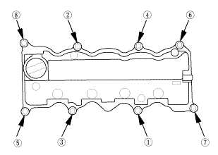
8.
|
Tighten the bolts in two steps. In the final step, torque all
bolts in sequence to 10 N·m (1.0 kgf·m, 7 lbf·ft).
|
|
NOTE:
|
|
|
Wait at least 30 minutes before filling the engine
with oil.
|
|
|
|
Do not run the engine for at least 3 hours after
installing the head cover.
|
|
|
|
|
|
|
9.
|
Connect the breather hose (A).
|
|
10.
|
Install the dipstick (B).
|
|
| 11. |
Cylinder Head Cover Peripheral Assembly |
|
 mmidnmm, mmidnmm,
|
|
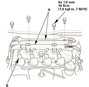
1.
|
Install the harness holders (A).
|
|
2.
|
Connect the connecters (B).
|
|
|
|
|
1.
|
Install the engine cover.
|
|
| 13. |
Idler Pulley Base Assembly |
|
|
|
1.
|
Install the idler pulley base.
|
|
| 14. |
Auto Tensioner Assembly |
|
 inl.25mmssn-m inl.25mmssn-m
|
|
1.
|
Install the drive belt auto-tensioner.
|
|
|
|
|
1.
|
Install the water pump pulley.
|
|
|
 mmn-m(2 mmn-m(2
|
|
1.
|
Install the alternator.
|
|
|
 i.nmm(n.i i.nmm(n.i
|
|
2.
|
Connect the connector and the cable. Make sure the crimped side
of the ring terminal faces away from the alternator when you connect
it.
|
|
3.
|
Install the harness connector (A) and the harness clamps (B).
|
|
|
|
|
1.
|
Move the auto-tensioner (A) counterclockwise.
|
|
2.
|
Install the drive belt (B).
|
|
| 18. |
Water Pump Pulley Mounting Bolt - Tighten |
|
|
|
1.
|
Tighten the water pump pulley mounting bolts.
|
|
|
1.
|
Install the splash shield (A).
|
| 20. |
Tire and Wheel-Installation, Front Right |
|
 mminmuan mminmuan
|
|
1.
|
Install the right front wheel.
|
|
NOTE: Before installing the wheel, clean the mating surfaces
between the brake disc and the inside of the wheel.
|
|
|
|
|
1.
|
Install the battery (A) and the battery setting plate (B).
|
|
NOTE: Do not deform the battery setting plate by over-tightening
the nuts.
|
|
| 22. |
Battery Terminal - Reconnection |
|
|
|
NOTE: If the battery performs abnormally, test the battery.
|
|
1.
|
Clean the battery terminals.
|
|
2.
|
Connect the positive cable (A) to the battery.
|
|
NOTE: Always connect the positive side first.
|
|
3.
|
Connect the negative cable and the battery sensor (B) to the
battery.
|
|
NOTE: To protect the battery sensor connector (C) from damage,
do not hold it when installing the negative terminal.
|
|
4.
|
Apply multipurpose grease to the terminals to prevent corrosion.
|
|
View
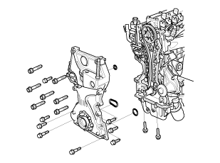
1.
Oil Pump Exploded View
Exploded View
mm27allon.pumpnowel......-m(1.2holder/bysoninbore
Disassembly
NOTE: Refer to the Exploded View ...
Replacement
1.
Sealing Bolt
NOTE: When installing the drain bolt and/or sealing bolt, always use
new washers.
l.5mm75mm35mmmmkglm,i25mm75
...
See also:
Honda Civic Owners Manual. Security System Alarm
The security system alarm activates when the trunk, hood or doors are
forcibly
opened. The alarm does not go off if the trunk or doors are opened with the key,
remote transmitter or smart entry system*.
However, the alarm activates if a door is opened with the key and then the shift
lever
...
 Engine Oil Pump Overhaul (K24Z7)
 Engine Block Drain Bolt/Sealing Bolt Removal and Installation (Except K24Z7)