Honda Civic Service Manual: Engine Oil/Air Separator Removal and Installation (R18Z1)
1111M5

Removal
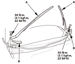
| 1. | Wiper Arm Assembly |
|
|
|
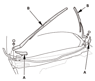
| 2. | Both Side Cowl Covers |
|
|
|
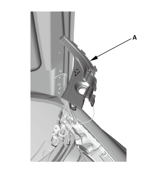
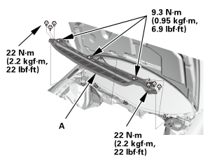
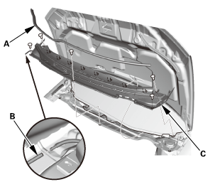
| 3. | Center Cowl Cover |
|
|
|

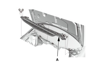
| 4. | Under Cowl Panel |
|
|
|
| 5. | Fuel Filler Cap |
|
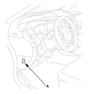
| 6. | HDS DLC - Connection |
|
|
|
| 7. | Fuel Pump Off |
|
||||||||||||||||||||||||

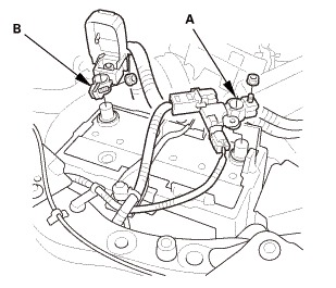
| 8. | Battery Terminal - Disconnection |
|
|
|
||||||||||||
| 9. | Fuel Pressure - Relieving |
|
|
|
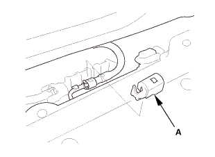
|
|
|
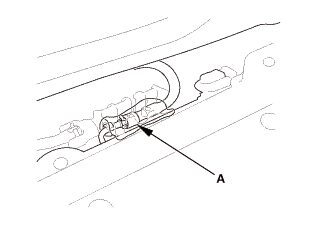
|
|
|
|||||||||||||||||||||||||
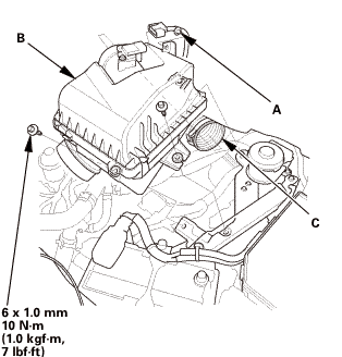
| 10. | Air Cleaner |
|
|
|
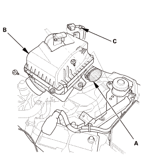
| 11. | Intake Air Duct |
|
|
|
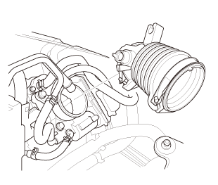
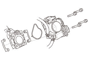
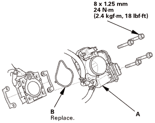
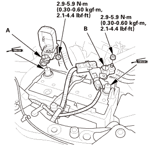
| 12. | Throttle Body - Removal |
|
|
|
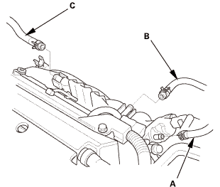
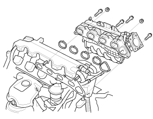
| 13. | Intake Manifold Assembly |
|
|
|
|
|
|
|
|
|
|
|
|
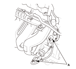
|
|
|
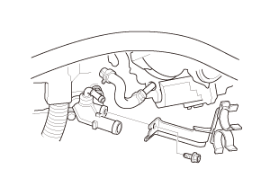
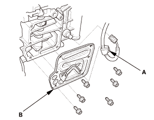
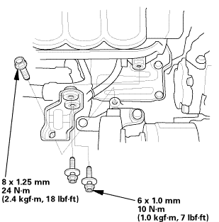
| 14. | Oil/Air Separator |
|
|
|

Installation
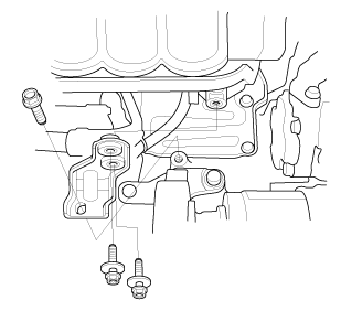
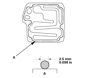
| 1. | Oil/Air Separator |
|
|
|
||||||||||||||||||||
|
|
|
||||||||||||||||||||
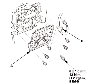 mm12
mm12| 2. | Intake Manifold Assembly |
|
|
|
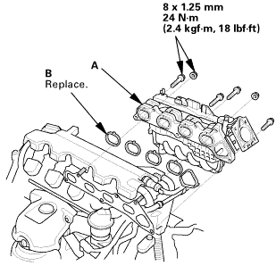 mm
mm|
|
|
|
|
|
|
|
|

|
|
|
| 3. | Throttle Body - Installation |
|
|
|
 mm
mm| 4. | Intake Air Duct |
|
|
|
| 5. | Air Cleaner |
|
|
|
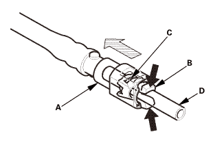
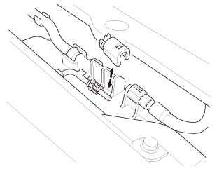
| 6. | Injector Base Fuel Feed Hose - Reconnection |
|
|
|
| 7. | Under Cowl Panel |
|
|
|
 22mm)2222
| 8. | Center Cowl Cover |
|
|
|
| 9. | Both Side Cowl Covers |
|
|
|
| 10. | Wiper Arm Assembly |
|
|
|
 1.122
1.122| 11. | Fuel Filler Cap |
|
| 12. | Battery Terminal - Reconnection |
|
|
|
||||||||||||||||
| 13. | HDS DLC - Connection |
|
|
|

| 14. | Fuel Pump On |
|
||||||||||
| 15. | Fuel Line Leak Check |
|
| 16. | Tubes, Hoses, and Connectors After Installation Check |
|
 Engine Oil Replacement
1.
Warm Up The Engine
1.
Warm up the engine.
2.
Vehicle Lift
...
 Engine Oil Pump Overhaul (K24Z7)
View
1.
Oil Pump Exploded View
Exploded View
mm27allon.pumpnowel......-m(1.2holder/bysoninbore
Disassembly
NOTE: Refer to the Exploded View ...
See also:
Honda Civic Service Manual. GPS Antenna Removal and Installation ('13)
1.
Dashboard Center Pocket
1.
Remove the screws (A).
2.
Remove the dashboard center pocket (A).
...
