Honda Civic Service Manual: Dashboard/Steering Hanger Beam Removal and Installation (Natural Gas models)
8411J6

| 1. |
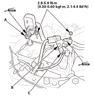
Battery Terminal (SRS) - Disconnection |
|
|
|
1.
|
Make sure the ignition switch is in LOCK (0).
|
|
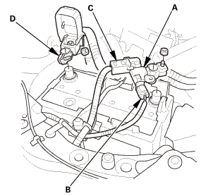
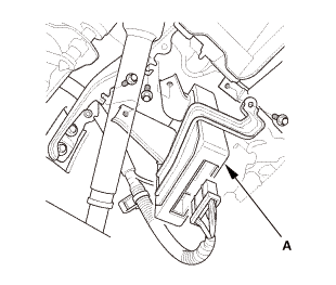
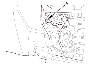
2.
|
Disconnect and isolate the negative cable with the battery sensor
(A) from the battery.
|
|
NOTE:
|
|

|
Always disconnect the negative side first.
|
|
|
|
To protect the battery sensor connector (B) from
damage, do not hold it when removing the negative
terminal.
|
|
|
|
Do not disconnect the battery sensor from the
negative terminal (C).
|
|
|
|
3.
|
Disconnect the positive cable (D) from the battery.
|
|
4.
|
Wait at least 3 minutes before starting work.
|
|
| 2. |
Front Door Opening Seal As Needed Both |
|

|
|
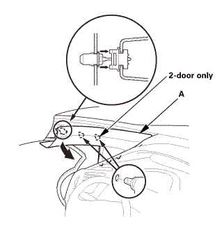
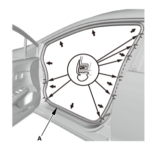
1.
|
Remove front door opening seal (A) as needed.
|
|
2.
|
Repeat on the opposite side.
|
|
|
|
|
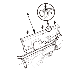
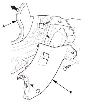
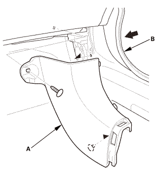
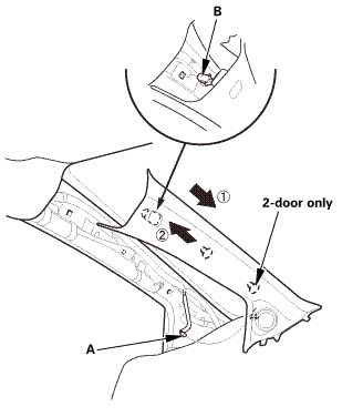
1.
|
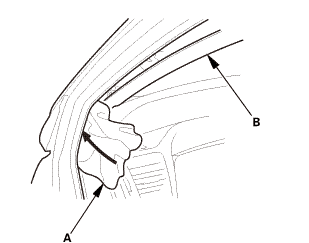
Pull out the A-pillar trim (A) to release the clips.
|
|
|
|
|
2.
|
Put a shop towel (A) in the opening between the A-pillar trim
(B) and the dashboard to prevent dropping the A-pillar clips.
|
|
|
|
|
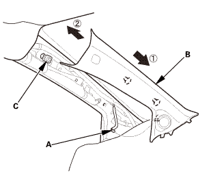
3.
|
Disconnect the connector (A), then remove the A-pillar trim (B).
|
|
NOTE: The upper clip (C) will stay in the body.
|
|
|
|
|
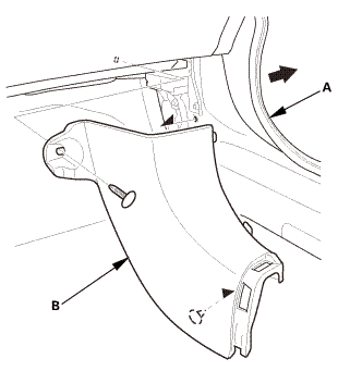
4.
|
Remove the upper clip (A) from the body.
|
|
5.
|
Repeat on the opposite side.
|
|
| 4. |
Driver's Dashboard Lower Cover |
|
|
|
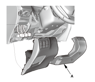
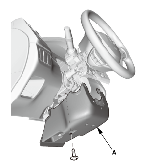
1.
|
Remove the driver's dashboard lower cover (A).
|
|
| 5. |
Both Front Door Sill Trims |
|

|
|
1.
|
Driver's side: Remove the cap (A) from the front door sill trim
(B).
|
|
2.
|
Driver's side: Remove the opener lock cylinder (C).
|
|
|
|
|
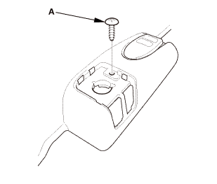
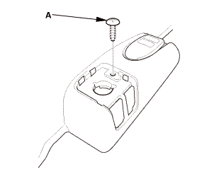
3.
|
Driver's side: Remove the screw (A).
|
|
|
Driver's side
Passenger's side

|
|
4.
|
Remove both front door sill trims (A).
|
|
|
Driver's side
Passenger's side
|
|
1.
|
Pull out both front door opening seals (A) as needed.
|
|
2.
|
Remove both kick panels (B).
|
|
|
|
|
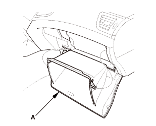
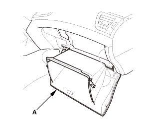
1.
|
Lower the glove box (A).
|
|
| 8. |
Center Console Panel Assembly (Except '12M M/T) |
|
|
|
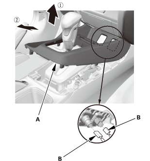
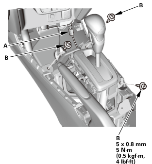
2.
|
Remove the center console panel (A).
|
|
3.
|
For some models: Disconnect the connector(s) (B).
|
|
| 9. |
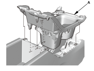
Cup Holder Panel Assembly |
|
|
|
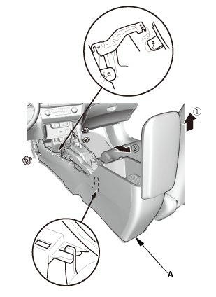
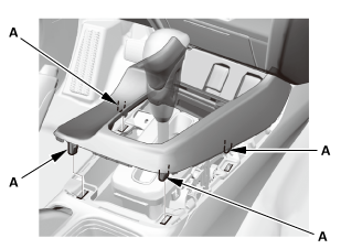
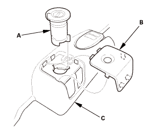
1.
|
Remove the cup holder panel assembly (A).
|
|
|
|
|
2.
|
Disconnect the connector (B).
|
|
|
|
|
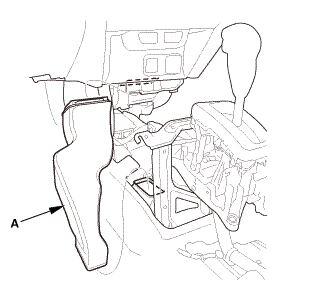
3.
|
Remove the console box mat (A).
|
|
|
|
|
5.
|
Disconnect the connector (A).
|
|
|
|
|
6.
|
Remove the center console (A).
|
|
| 11. |
Rear Heater Joint Duct |
|
|
|
1.
|
Remove the rear heater joint duct (A).
|
|
| 12. |
Center Console Base Bracket |
|
|
|
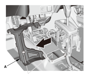
1.
|
Remove the center console base bracket (A).
|
|
|
|
|
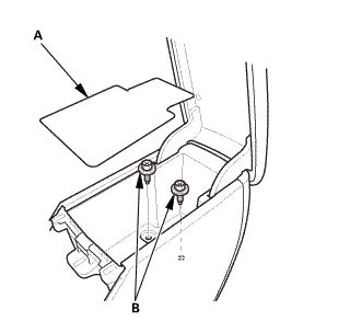
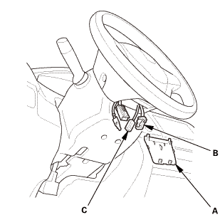
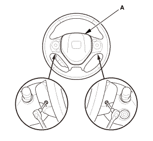
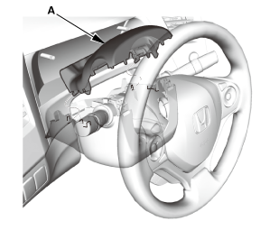
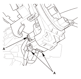
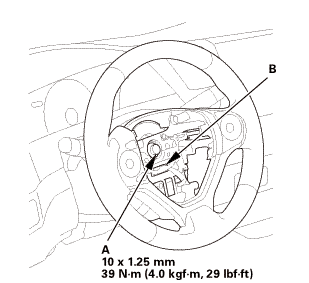
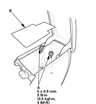
1.
|
Remove the access panel (A).
|
|
2.
|
Disconnect the driver's airbag inflator connector (B) on the
cable reel harness.
|
|
3.
|
Disconnect the horn switch connector (C).
|
|
|
|
|
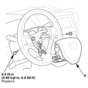
4.
|
Remove the TORX bolts using a TORX T30 bit.
|
|
5.
|
Remove the driver's airbag (A).
|
|
| 14. |
Steering Wheel Assembly |
|
 wxusmm wxusmm
|
|
1.
|
Set the front wheels in the straight ahead position.
|
|
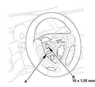
2.
|
Disconnect the connector (A).
|
|
3.
|
Loosen the steering wheel bolt (B) three turns.
|
|
|
|
|
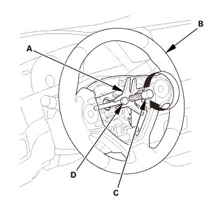
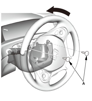
4.
|
Install a commercially available steering wheel puller (A) on
the steering wheel (B).
|
|
5.
|
Free the steering wheel from the steering column shaft by turning
the pressure bolt (C) of the puller.
|
|
Note these items when removing the steering wheel:
|
|
|
Do not tap on the steering wheel or the steering
column shaft when removing the steering wheel.
|
|
|
|
If you thread the puller bolts (D) into the wheel
hub more than five threads, the bolts will hit the
cable reel and damage it. To prevent this, install
a pair of jam nuts five threads up on each puller
bolt.
|
|
|
|
|
|
|
6.
|
Remove the steering wheel puller.
|
|
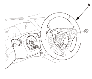
7.
|
Remove the steering wheel (A) from the steering column.
|
|
|
|
|
1.
|
Remove the upper column cover (A).
|
|
|
|
|
1.
|
Remove the screws (A).
|
|
|
|
|
2.
|
Remove the lower column cover (A).
|
|
| 17. |
Combination Switch Body Assembly |
|
|
|
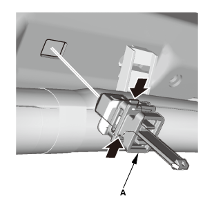
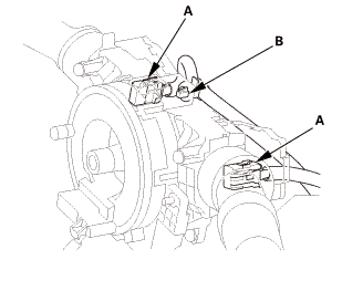
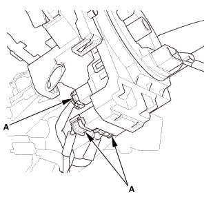
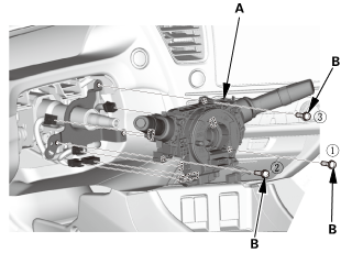
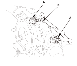
1.
|
Disconnect the connectors (A).
|
|
|
|
|
3.
|
Disconnect the connectors (A).
|
|
|
Without steering lock
With steering lock
|
|
4.
|
Remove the combination switch body assembly (A) from the steering
column shaft.
|
|
|
|
|
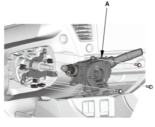
1.
|
Remove the steering joint cover (A).
|
|
| 19. |
Steering Column Lower Slide Shaft - Hold |
|
|
|
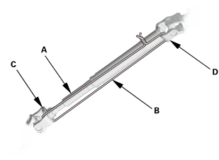
1.
|
Set the steering column to the center tilt position, and to the
center telescopic position.
|
|
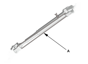
2.
|
Hold the lower slide shaft (A) on the column with a piece of
wire (B) between the joint yoke (C) of the lower slide shaft and
the joint yoke (D) of the upper shaft to prevent the lower slider
shaft from pulling out.
|
|
| 20. |
Steering Joint Bolt - Loosen |
|
|
|
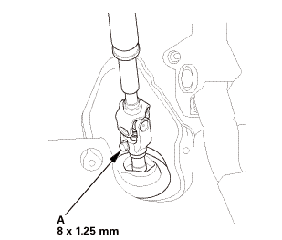
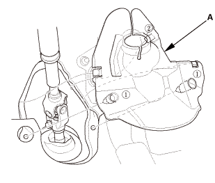
1.
|
Loosen the steering joint bolt (A).
|
|
| 21. |
Steering Joint - Disconnection |
|
|
|
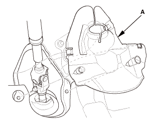
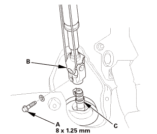
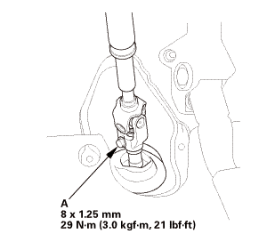
1.
|
Remove the steering joint bolt (A).
|
|
2.
|
Disconnect the steering joint (B) from the pinion shaft.
|
|
NOTE:
|
|
|
If the center guide (C) is in place and has not
moved, leave it in place.
|
|
|
|
If the center guide has come off, discard it.
|
|
|
|
|
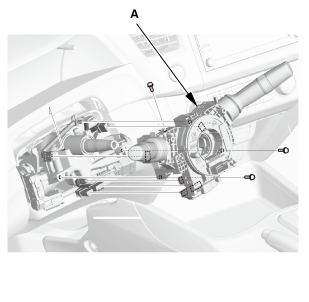
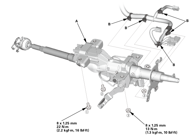
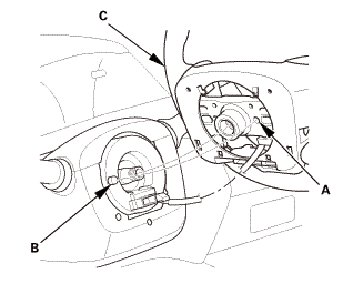
1.
|
With steering lock: Disconnect the connectors (A) from the ignition switch
(B).
|
Without steering lock
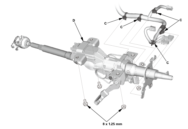
With steering lock
|
2.
|
Detach the wire harness clips (C) from the steering column.
|
|
3.
|
Remove the steering column (D).
|
|
NOTE: Do not release the lock lever until the steering column is installed.
If the lock lever is released before installation, adjust the steering column
after installation.
|
| 23. |
Injector Control Module (Natural Gas Model) |
|
|
|
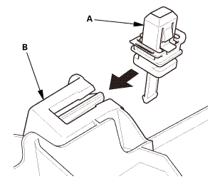
1.
|
Remove the injector control module (A).
|
|
| 24. |
A-Pillar Corner Trim Both |
|
|
|
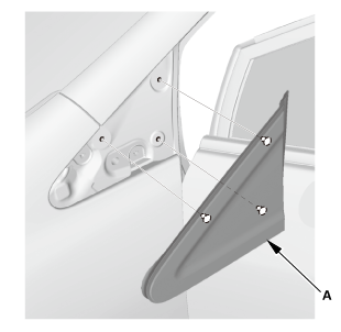
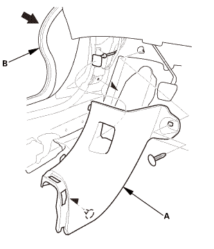
1.
|
Remove both A-pillar corner trims (A).
|
|
| 25. |
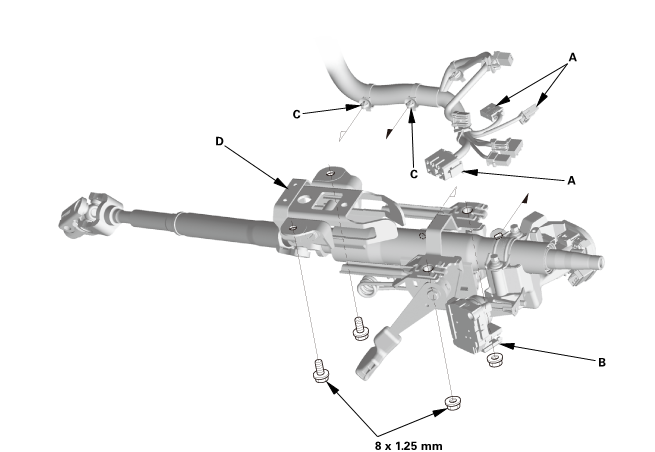
Dashboard/Steering Hanger Beam |
|
|
|
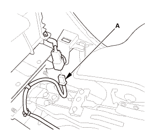
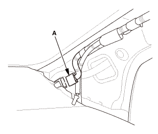
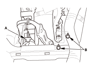
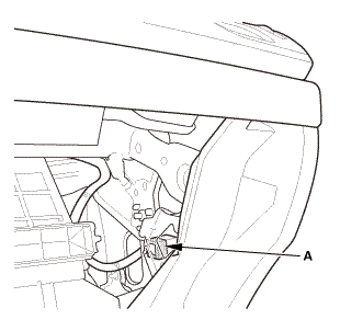
1.
|
Disconnect the connector (A).
|
|
|
|
|
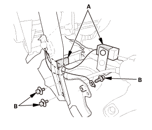
2.
|
Disconnect the connectors (A).
|
|
|
|
|
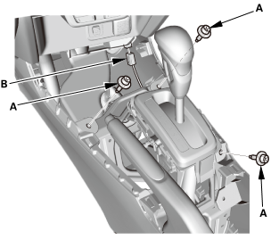
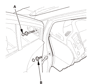
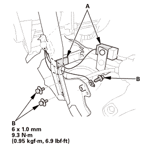
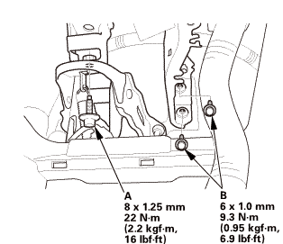
3.
|
Remove the bolts (A, B) from under the dash.
|
|
|
|
|
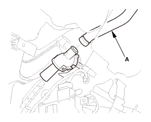
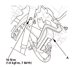
4.
|
With climate control: Remove the aspirator hose (A).
|
|
|
|
|
5.
|
Disconnect the connectors (A).
|
|
|
|
|
7.
|
Disconnect the connector (A).
|
|
|
|
|
8.
|
Disconnect the connector (A).
|
|
|
|
|
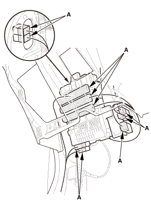
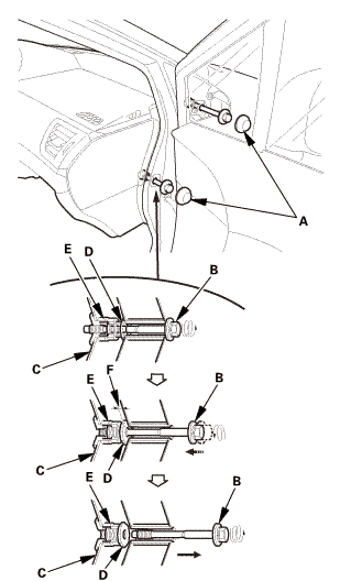
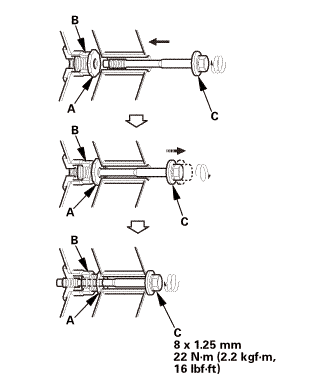
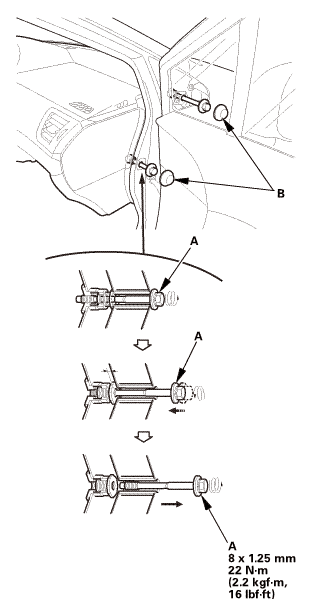
10.
|
Loosen the special bolts (B) until they disengage from the threads
on the hanger beam side brackets (C), and engage the inside threads
of the collar bolts (D). The thread lock on the special bolts makes
the special bolts and the collar bolts turn together.
|
|
11.
|
Continue to loosen the special bolts to turn the collar bolts
into the fixed space adjusters (E) until the collar bolts engage
the adjuster brackets. This creates a gap (F) between the collar
bolts and the body.
|
|
12.
|
Remove the special bolts.
|
|
|
|
|
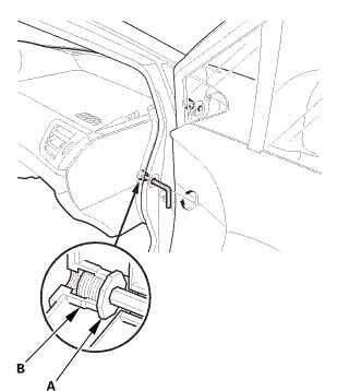
13.
|
Check that the collar bolts (A) are seated in the fixed space
adjusters (B).
|
|
NOTE: If either collar bolt was not seated, replace the special
bolts.
|
|
|
|
|
15.
|
Remove the bolts (B).
|
|
|
|
|
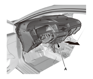
16.
|
Remove the dashboard (A).
|
|

| 1. |
Dashboard/Steering Hanger Beam |
|
Special bolt tightening on passenger's side
 mm22(2.2 mm22(2.2
|
|
|
Make sure the collar bolts (A) turn easily by hand in
the fixed space adjusters (B). Tighten the collar bolts
by hand until they engage the fixed space adjusters before
reinstalling the dashboard.
|
|
|
|
Before reinstalling the dashboard, screw the special
bolts (C) into the collar bolts, and check that they turn
together. If they do not turn together, replace the special
bolts.
|
|
|
|

|
|
1.
|
Install the dashboard (A).
|
|
|
|
|
2.
|
Install the bolts (A).
|
|
|
|
|
4.
|
Install the special bolts (A).
|
|
|
|
|
6.
|
Connect the connector (A).
|
|
|
|
|
7.
|
Connect the connector (A).
|
|
|
 mmmm mmmm
|
|
8.
|
Connect the connectors (A).
|
|
9.
|
Install the bolts (B).
|
|
|
|
|
10.
|
With climate control: Install the aspirator hose (A).
|
|
|
 ixi2mm22(2.2asin ixi2mm22(2.2asin
|
|
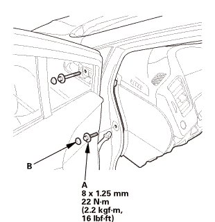
11.
|
Install the bolts (A, B) under the dash.
|
|
|

|
|
12.
|
Connect the connectors (A).
|
|
|
|
|
13.
|
Connect the connector (A).
|
|
| 2. |
A-Pillar Corner Trim Both |
|
|
|
1.
|
Install both A-pillar corner trims (A).
|
|
| 3. |
Injector Control Module (Natural Gas Model) |
|
|
|
1.
|
Install the injector control module (A).
|
|
|
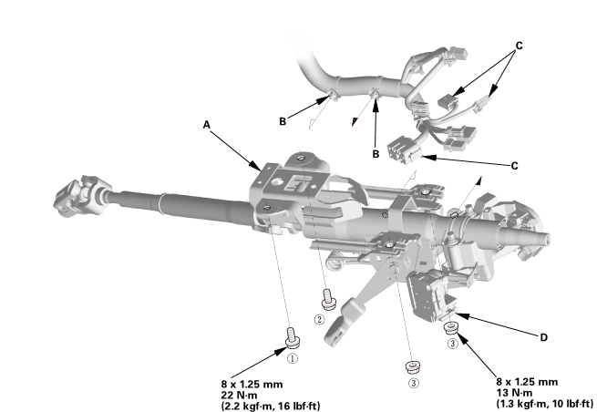
1.
|
Install the steering column (A).
|
|
NOTE: Do not release the lock lever until the steering column is installed.
If the lock lever is released before installation, adjust the steering column
after installation.
|
Without steering lock
 22(22mm)
With steering lock
 u.
u.
|
2.
|
Loosely tighten the attaching nuts and bolts.
|
|
3.
|
Tighten the attaching nuts and bolts to the specified torque in the sequence
shown.
|
|
4.
|
Install the wire harness clips (B) to the steering column.
|
|
5.
|
With steering lock: Connect the connectors (C) to the ignition switch
(D).
|
| 5. |
Steering Joint - Reconnection |
|
|
|
1.
|
Set the rack in the straight ahead driving position.
|
|
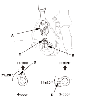
2.
|
Slip the lower end of the steering joint (A) onto the pinion
shaft (B).
|
|
NOTE:
|
|
|
Pinion shaft with center guide: Install the steering
joint by aligning the center guide (C).
|
|
|
|
Pinion shaft without center guide: Position the
steering column by aligning the gap (D) within the
angle.
|
|
|
|
|
|
|
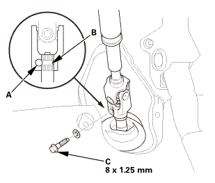
3.
|
Align the bolt hole (A) on the steering joint with the groove
(B) around the pinion shaft.
|
|
4.
|
Loosely install the steering joint bolt (C).
|
|
5.
|
Be sure that the joint bolt is securely in the groove in the
pinion shaft.
|
|
6.
|
Pull on the steering joint to make sure that the steering joint
is fully seated.
|
|
| 6. |
Steering Joint Bolt - Tighten |
|
 mm:.o21 mm:.o21
|
|
1.
|
Tighten the steering joint bolt (A) to the specified torque.
|
|
| 7. |
Steering Column Lower Slide Shaft - Release |
|
|
|
1.
|
Install the steering joint cover (A) in the sequence shown.
|
|
| 9. |
Combination Switch Body Assembly |
|
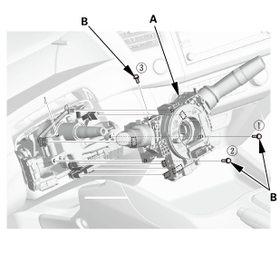
Without steering lock
With steering lock
|
|
1.
|
Install the combination switch body assembly (A).
|
|
2.
|
Tighten three screws (B) in the sequence shown.
|
|
|
|
|
3.
|
Connect the connectors (A).
|
|
|
|
|
4.
|
Connect the connectors (A).
|
|
|
|
|
1.
|
Install the lower column cover (A).
|
|
|
|
|
2.
|
Install the screws (A).
|
|
|

|
|
1.
|
Install the upper column cover (A).
|
|
| 12. |
Steering Wheel Assembly |
|
|
|
1.
|
Make sure the front wheels are pointing straight ahead.
|
|
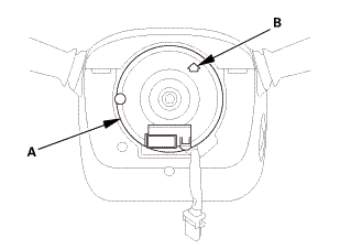
2.
|
Center the cable reel (A). Do this by first rotating the cable
reel clockwise until it stops.
|
|
3.
|
Rotate the cable reel counterclockwise about three full turns.
The arrow mark (B) on the cable reel label should point straight
up.
|
|
|
|
|
4.
|
Position the steering wheel hub (A) so that it engages the pin
(B) of the cable reel.
|
|
5.
|
Install the steering wheel (C) on to the steering column shaft.
|
|
NOTE: Do not tap on the steering wheel or the steering column
shaft when installing the steering wheel.
|
|
|
 no no
|
|
6.
|
Install the steering wheel bolt (A), and tighten it to the specified
torque.
|
|
7.
|
Connect the connector (B).
|
|
8.
|
Make sure the wire harness is routed and fastened properly.
|
|
|
 mmmmin)in! mmmmin)in!
|
|
NOTE: If you are replacing a deployed driver's airbag, inspect
the cable reel for heat damage. If there is any damage, replace
the cable reel.
|
|
1.
|
Place the driver's airbag (A) in the steering wheel.
|
|
2.
|
Tighten the new TORX bolts using a TORX T30 bit.
|
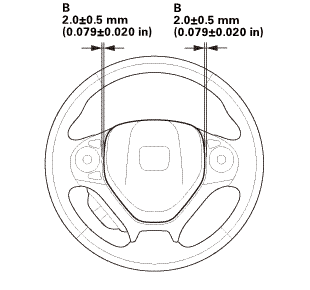
|
NOTE: Make sure the clearance (B) between the steering wheel
and horn pad is the specified value.
|
|
|

|
|
3.
|
Connect the driver's airbag inflator connector (A) on the cable
reel harness.
|
|
4.
|
Connect the horn switch connector (B).
|
|
NOTE: After reconnecting the negative cable to the battery, make
sure the horn works properly.
|
|
5.
|
Install the access panel (C).
|
|
| 14. |
Center Console Base Bracket |
|

|
|
1.
|
Install the center console base bracket (A).
|
|
| 15. |
Rear Heater Joint Duct |
|
|
|
1.
|
Install the rear heater joint duct (A).
|
|
|

|
|
1.
|
Install the center console (A).
|
|
|
|
|
2.
|
Connect the connector (A).
|
|
|
|
|
3.
|
Install the bolts (A).
|
|
4.
|
Install the console box mat (B).
|
|
|
|
|
5.
|
Connect the connector (A).
|
|
6.
|
Install the bolts (B).
|
|
| 17. |
Cup Holder Panel Assembly |
|
|
|
1.
|
Install the cup holder panel assembly (A).
|
|
| 18. |
Center Console Panel Assembly (Except '12M M/T) |
|

|
|
1.
|
For some models: Connect the connector(s) (A).
|
|
2.
|
Install the center console panel (B).
|
|
|
|
|
3.
|
Install the clips (A).
|
|
|
|
|
1.
|
Install the glove box (A).
|
|
|
Driver's side
Passenger's side
|
|
1.
|
Install both kick panels (A).
|
|
2.
|
Install both front door opening seals (B) as needed.
|
|
| 21. |
Both Front Door Sill Trims |
|
Driver's side
Passenger's side
|
|
1.
|
Install both front door sill trims (A).
|
|
|
|
|
2.
|
Driver's side: Install the screw (A).
|
|
|
|
|
3.
|
Driver's side: Install the opener lock cylinder (A).
|
|
4.
|
Driver's side: Install the cap (B) to the front door sill trim
(C).
|
|
| 22. |
Driver's Dashboard Lower Cover |
|
|
|
1.
|
Install the driver's dashboard lower cover (A).
|
|
|
|
|
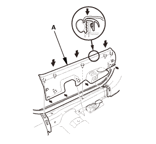
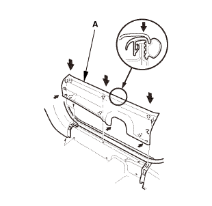
1.
|
Carefully install the new upper clip (A) to the A-pillar trim
(B).
|
|
|
|
|
2.
|
Connect the connector (A).
|
|
3.
|
Fit the clips into the holes in the A-pillar.
|
|
4.
|
Lightly push the A-pillar trim (B) into place, then install the
trim.
|
|
NOTE:
|
|
|
Make sure the side curtain airbag is not tucked
under the clips or the trim ribs.
|
|
|
|
Do not push too hard on the A-pillar trim. If
you push too hard, the clip will be damaged, and
it will not hold the trim properly.
|
|
|
|
Gently tug on the A-pillar trim to verify that
all clips are securely fastened.
|
|
|
|
5.
|
Repeat on the opposite side.
|
|
| 24. |
Front Door Opening Seal as Needed Both |
|
|
|
1.
|
Install front door opening seal (A).
|
|
2.
|
Repeat on the opposite side.
|
|
| 25. |
Battery Terminal (SRS) - Reconnection |
|
 (o.2ao.sam. (o.2ao.sam.
|
|
NOTE: If the battery performs abnormally, test the battery.
|
|
1.
|
Clean the battery terminals.
|
|
2.
|
Connect the positive cable (A) to the battery.
|
|
NOTE: Always connect the positive side first.
|
|
3.
|
Connect the negative cable and the battery sensor (B) to the
battery.
|
|
NOTE: To protect the battery sensor connector (C) from damage,
do not hold it when installing the negative terminal.
|
|
4.
|
Apply multipurpose grease to the terminals to prevent corrosion.
|
|
|
|
|
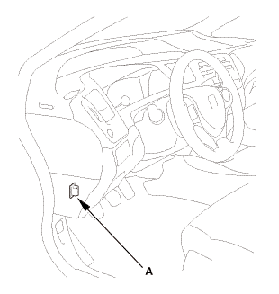
1.
|
Connect the HDS to the data link connector (DLC) (A) located
under the driver's side of the dashboard.
|
|
2.
|
Turn the ignition switch to ON (II).
|
|
3.
|
Make sure the HDS communicates with the vehicle. If it does not
communicate, go to the DLC circuit troubleshooting.
|
|
|
|
1.
|
Clear the DTC(s) by following the screen prompts on the HDS.
|
|
2.
|
Turn the ignition switch to LOCK (0), then wait for 10 seconds.
|
|
| 28. |
Confirm Proper SRS Operation |
|
|
Turn the ignition switch to ON (II), and check that the SRS indicator
comes on for about 6 seconds and then goes off.
|
|
| 29. |
VSA Sensor Neutral Position - Memorization |
|
|
1.
|
Park the vehicle on a flat and level surface, with the steering
wheel in the straight ahead position.
|
|
2.
|
Select VSA ADJUSTMENT, then select ALL SENSORS with the HDS,
and follow the screen prompts.
|
|
NOTE: See the HDS Help menu for specific instructions.
|
|
| 30. |
Steering Angle Sensor Neutral Position - Clear |
|
|
1.
|
Select EPS ADJUSTMENT, then select EPS STEERING ANGLE SENSOR
VALUE CLEAR and follow the screen prompts on the HDS.
|
|
NOTE: See the HDS Help menu for specific instructions.
|
|
SRS components are located in this area. Review the SRS component locations
and the precautions and procedures before doing repairs or service.
1.
Dashboard Su ...
1.
Driver's Outer Vent
1.
Remove the driver's outer vent (A).
...
See also:
Honda Civic Owners Manual. Locking/Unlocking the Doors Using a Key
If the keyless remote battery or the vehicle battery is dead, use the key
instead of the
keyless remote.
Fully insert the key and turn it.
Locking/Unlocking the Doors Using a Key
When you lock the driver’s door with a key, all the
other doors lock at the same time. When unlocking,
the ...
 Dashboard/Steering Hanger Beam Disassembly and Reassembly (Without Navigation)
 Driver's Outer Vent Removal and Installation ('13-'14)