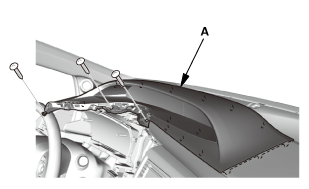
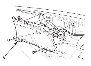
Honda Civic Service Manual: Dashboard/Steering Hanger Beam Disassembly and Reassembly (Without Navigation)

|
SRS components are located in this area. Review the SRS component locations and the precautions and procedures before doing repairs or service. |
| 1. | Dashboard Subdisplay Visor |
|
|
|
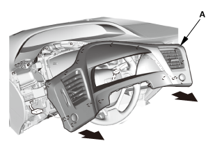
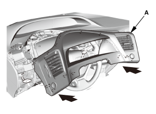
| 2. | Dashboard Meter Visor |
|
|
|
| 3. | Gauge Control Module - Tach |
|
|
|

| 4. | Information Display Unit |
|
|
|
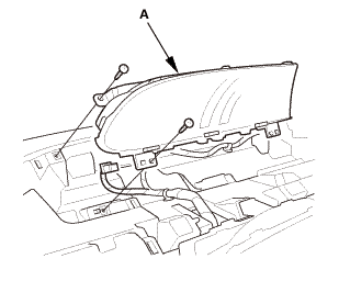
| 5. | Multi-Information Display Unit |
|
|
|
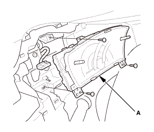
| 6. | Gauge Control Module - Speedo |
|
|
|

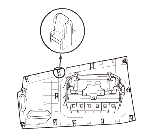
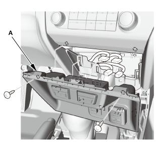
| 7. | Center Lower Panel |
|
|
|
||||||

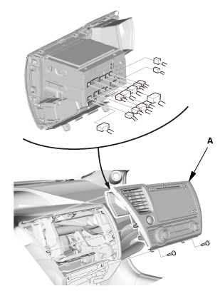
| 8. | Audio Unit Assembly |
|
|
|

|
|
|
| 9. | Audio Unit Assembly (With display audio) |
|
|
|
|
|
|
| 10. | Front Passenger's Airbag Assembly |
|
|
|
|
|
|
||||||
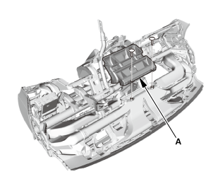
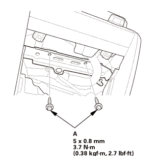
| 11. | Center Joint Duct |
|
|
|
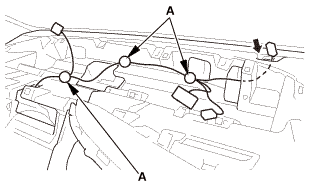
|
|
|
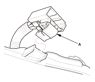
|
|
|
|
|
|
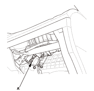
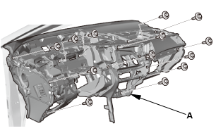
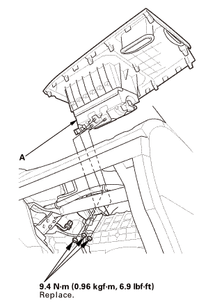
| 12. | Steering Hanger Beam |
|
|
|

|
SRS components are located in this area. Review the SRS component locations and the precautions and procedures before doing repairs or service. |
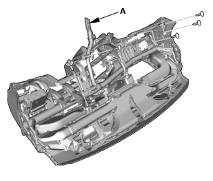
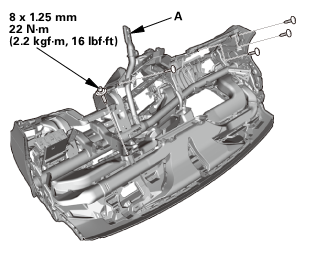
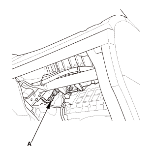
| 1. | Steering Hanger Beam |
|
|
|
 mm22u....z1
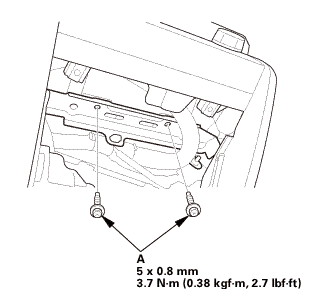
| 2. | Center Joint Duct |
|
|
|
|
|
|
 mmto
mmto|
|
|
|
|
|
| 3. | Front Passenger's Airbag Assembly |
|
|
|
|
|
|
| 4. | Audio Unit Assembly (With display audio) |
|
|
|
||||||
|
|
|
| 5. | Audio Unit Assembly |
|
|
|
||||||
|
|
|
 n.amm2.72.7
| 6. | Center Lower Panel |
|
|
|
||||||
| 7. | Gauge Control Module - Speedo |
|
|
|
| 8. | Multi-Information Display Unit |
|
|
|
| 9. | Information Display Unit |
|
|
|
| 10. | Gauge Control Module - Tach |
|
|
|
| 11. | Dashboard Meter Visor |
|
|
|

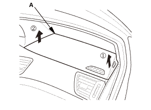
| 12. | Dashboard Subdisplay Visor |
|
|
|
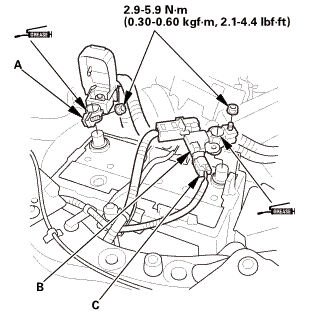
| 13. | Battery Terminal (SRS) - Reconnection |
|
|
|
|||||||||||||||||||
 (o.2ao.sam.
 Dashboard/Steering Hanger Beam Disassembly and Reassembly (With Navigation)
SRS components are located in this area. Review the SRS component locations
and the precautions and procedures before doing repairs or service.
1.
Dashboard Su ...
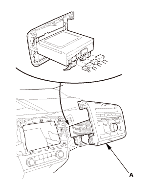
 GPS Antenna Removal and Installation ('13)
1.
Dashboard Center Pocket
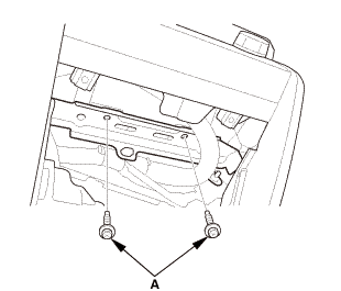
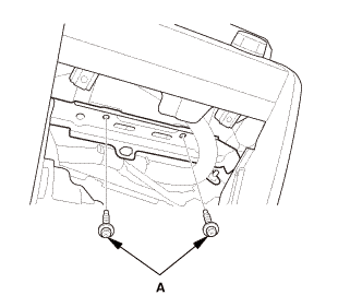
1.
Remove the screws (A).
...
See also:
Honda Civic Owners Manual. Advanced Airbags
The airbags have advanced features to help reduce the likelihood of airbag
related
injuries to smaller occupants.
The driver’s advanced airbag system includes a
seat position sensor.
Based on information from this sensor and the
severity of the impact, the advanced airbag
system dete ...
