Honda Civic Service Manual: Cruise Control Combination Switch Removal, Installation, and Test
738125

Removal
|
There are SRS components located in this area. Review the SRS component
locations, and the precautions and procedures, in the SRS before doing repairs
or service.
|
| 1. |
Battery Terminal (SRS) - Disconnection |
|
|
|
1.
|
Make sure the ignition switch is in LOCK (0).
|
|
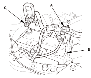
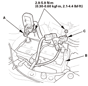
2.
|
Disconnect and isolate the negative cable and battery sensor
(A) from the battery (B).
|
|
NOTE: Always disconnect the negative side first.
|
|
3.
|
Disconnect the positive cable (C) from the battery.
|
|
4.
|
Wait at least 3 minutes before starting work.
|
|
|
|
|
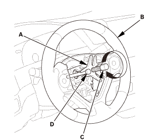
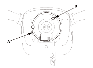
1.
|
Remove the access panel (A).
|
|
2.
|
Disconnect the driver's airbag inflator connector (B) on the
cable reel harness.
|
|
3.
|
Disconnect the horn switch connector (C).
|
|
|
|
|
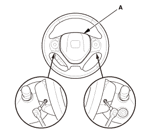
4.
|
Remove the TORX bolts using a TORX T30 bit.
|
|
5.
|
Remove the driver's airbag (A).
|
|
| 3. |
Steering Wheel Assembly |
|
 wxusmm wxusmm
|
|
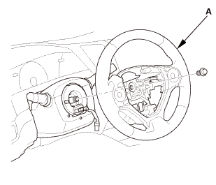
1.
|
Set the front wheels in the straight ahead position.
|
|
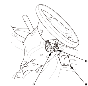
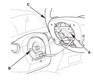
2.
|
Disconnect the connector (A).
|
|
3.
|
Loosen the steering wheel bolt (B) three turns.
|
|
|
|
|
4.
|
Install a commercially available steering wheel puller (A) on
the steering wheel (B).
|
|
5.
|
Free the steering wheel from the steering column shaft by turning
the pressure bolt (C) of the puller.
|
|
Note these items when removing the steering wheel:
|
|

|
Do not tap on the steering wheel or the steering
column shaft when removing the steering wheel.
|
|
|
|
If you thread the puller bolts (D) into the wheel
hub more than five threads, the bolts will hit the
cable reel and damage it. To prevent this, install
a pair of jam nuts five threads up on each puller
bolt.
|
|
|
|
|
|
|
6.
|
Remove the steering wheel puller.
|
|
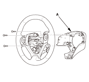
7.
|
Remove the steering wheel (A) from the steering column.
|
|
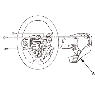
| 4. |
Steering Wheel Rear Cover |
|
|
|
1.
|
Remove the steering wheel rear cover (A).
|
|
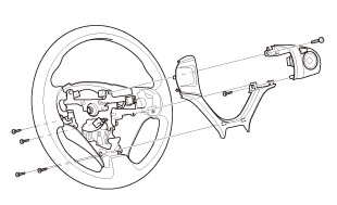
| 5. |
CRUISE CONTROL COMBINATION SWITCH |
|
|
|
1.
|
Remove the cruise control combination switch.
|
|
 Test
Test
| 1. |
CRUISE CONTROL COMBINATION SWITCH - TEST |
|
|
|
1.
|
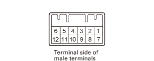
Measure the resistance between cruise control combination switch
12P connector terminal No. 2 and No. 5 according to the table.
|
|
If there is no resistance in one or more positions, replace the
cruise control combination switch.
|
|
|
Position
|
Resistance
|
|
OFF
|
About 2.2 k?
|
|
Cruise control main (PRESSED)
|
About 60 ?
|
|
Cancel (PRESSED)
|
About 190 ?
|
|
Set/- (PRESSED)
|
About 450 ?
|
|
Res/+ (PRESSED)
|
About 900 ?
|
|
|
|
|
|
 pusllwnswilch(am pusllwnswilch(am
|
|
2.
|
Check for continuity between cruise control combination switch
12P connector terminal No. 1 and No. 6 according to the table.
|
|
If there is no continuity, replace the cruise control combination
switch.
|
|

Installation
|
There are SRS components located in this area. Review the SRS component
locations, and the precautions and procedures, in the SRS before doing repairs
or service.
|
| 1. |
CRUISE CONTROL COMBINATION SWITCH |
|
|
|
1.
|
Install the Install the cruise control combination switch.
|
|
| 2. |
Steering Wheel Rear Cover |
|
|
|
1.
|
Install the steering wheel rear cover (A).
|
|
| 3. |
Steering Wheel Assembly |
|
|
|
1.
|
Make sure the front wheels are pointing straight ahead.
|
|
2.
|
Center the cable reel (A). Do this by first rotating the cable
reel clockwise until it stops.
|
|
3.
|
Rotate the cable reel counterclockwise about three full turns.
The arrow mark (B) on the cable reel label should point straight
up.
|
|
|
|
|
4.
|
Position the steering wheel hub (A) so that it engages the pin
(B) of the cable reel.
|
|
5.
|
Install the steering wheel (C) on to the steering column shaft.
|
|
NOTE: Do not tap on the steering wheel or the steering column
shaft when installing the steering wheel.
|
|
|
 no no
|
|
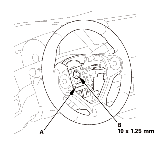
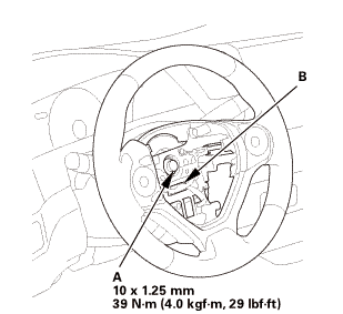
6.
|
Install the steering wheel bolt (A), and tighten it to the specified
torque.
|
|
7.
|
Connect the connector (B).
|
|
8.
|
Make sure the wire harness is routed and fastened properly.
|
|
|
 mmmmin)in! mmmmin)in!
|
|
NOTE: If you are replacing a deployed driver's airbag, inspect
the cable reel for heat damage. If there is any damage, replace
the cable reel.
|
|
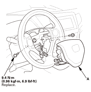
1.
|
Place the driver's airbag (A) in the steering wheel.
|
|
2.
|
Tighten the new TORX bolts using a TORX T30 bit.
|
|
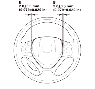
NOTE: Make sure the clearance (B) between the steering wheel
and horn pad is the specified value.
|
|
|

|
|
3.
|
Connect the driver's airbag inflator connector (A) on the cable
reel harness.
|
|
4.
|
Connect the horn switch connector (B).
|
|
NOTE: After reconnecting the negative cable to the battery, make
sure the horn works properly.
|
|
5.
|
Install the access panel (C).
|
|
| 5. |
Battery Terminal (SRS) - Reconnection |
|
 (o.2ao.sam. (o.2ao.sam.
|
|
NOTE: If the battery performs abnormally, test the battery.
|
|
1.
|
Clean the battery terminals.
|
|
2.
|
Connect the positive cable (A) to the battery (B).
|
|
NOTE: Always connect the positive side first.
|
|
3.
|
Connect the negative cable and battery sensor (C) to the battery.
|
|
4.
|
Apply multipurpose grease to the terminals to prevent corrosion.
|
|
|

|
|
1.
|
Connect the HDS to the data link connector (DLC) (A) located
under the driver's side of the dashboard.
|
|
2.
|
Turn the ignition switch to ON (II).
|
|
3.
|
Make sure the HDS communicates with the vehicle. If it does not
communicate, go to the DLC circuit troubleshooting.
|
|
| 7. |
VSA Sensor Neutral Position - Memorization |
|
|
1.
|
Park the vehicle on a flat and level surface, with the steering
wheel in the straight ahead position.
|
|
2.
|
Select VSA ADJUSTMENT, then select ALL SENSORS with the HDS,
and follow the screen prompts.
|
|
NOTE: See the HDS Help menu for specific instructions.
|
|
| 8. |
Steering Angle Sensor Neutral Position - Clear |
|
|
1.
|
Select EPS ADJUSTMENT, then select EPS STEERING ANGLE SENSOR
VALUE CLEAR and follow the screen prompts on the HDS.
|
|
NOTE: See the HDS Help menu for specific instructions.
|
|
| 9. |
Confirm Proper SRS Operation |
|
|
Turn the ignition switch to ON (II), and check that the SRS indicator
comes on for about 6 seconds and then goes off.
|
|
1.
Trunk Lid Trim Panel
1.
Remove the trunk lid trim panel (A).
2.
...
1.
LaneWatch Camera Aiming
NOTE: The LaneWatch camera must be aimed after one or more of
the following procedures are done:
...
See also:
Honda Civic Owners Manual. What to Do After the Engine Starts
Once your vehicle's engine has started, remove the jumper cables in the
following
order.
Disconnect the jumper cable from your vehicle's ground.
Disconnect the other end of the jumper cable from the booster
battery -
terminal.
Disconnect the jumper cable from your v ...
 Rearview Camera Removal and Installation ('13-'14)
 LaneWatch Camera Aiming