Honda Civic Service Manual: Connecting Rod Bearing Replacement (R18Z1)

Removal
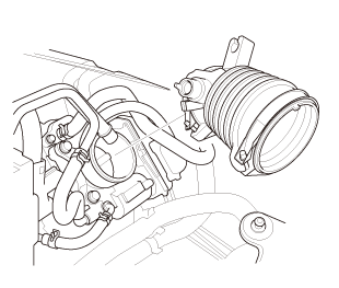
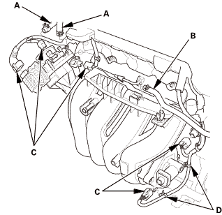
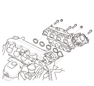
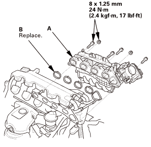
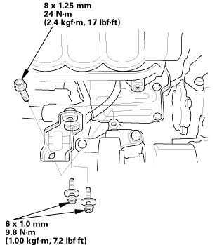
| 1. | Intake Manifold and Throttle Body Assembly |
|
|
|
|
|
|
|
|
|
|
|
|
|
|
|
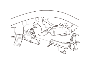
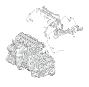
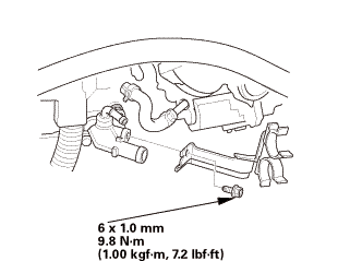
| 2. | Engine Wire Harness |
|
|
|
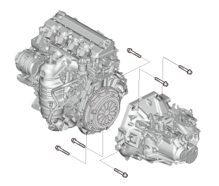
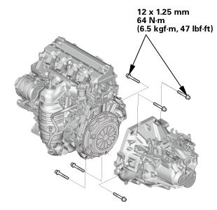
| 3. | Manual Transmission Assembly (M/T) |
|
|
|
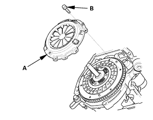
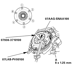
| 4. | Pressure Plate |
|
|
|
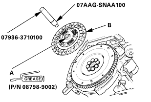
| 5. | Clutch Disc |
|
|
|
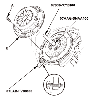
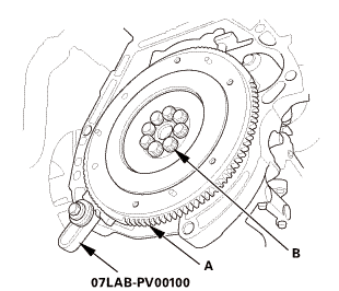
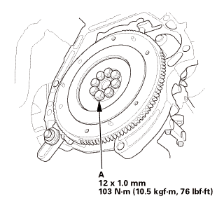
| 6. | Flywheel |
|
|
|
|||||||||
 n7lab-wnolun
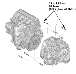
| 7. | Automatic Transmission Assembly (A/T) |
|
|
|
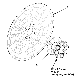
| 8. | Drive Plate Assembly |
|
|
|
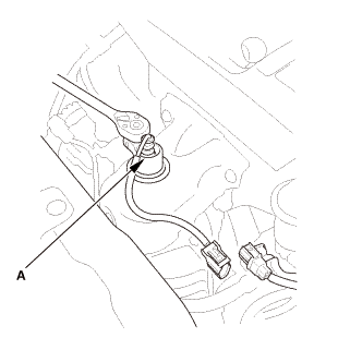
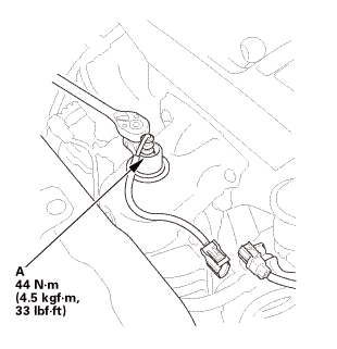
| 9. | A/F Sensor (Sensor 1) |
|
|
|
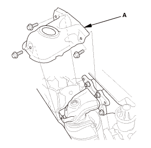
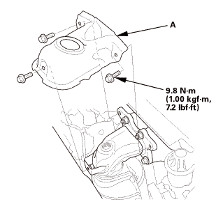
| 10. | Exhaust Chamber Cover |
|
|
|
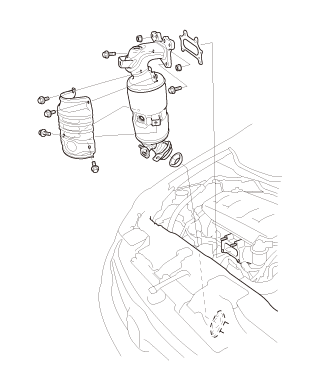
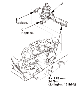
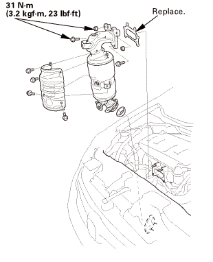
| 11. | Catalytic Converter and EGR Pipe Assembly |
|
|
|
|
|
|
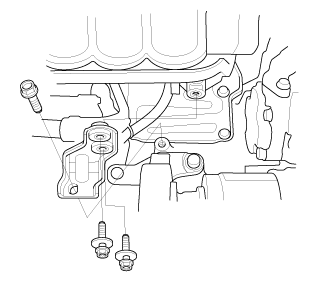
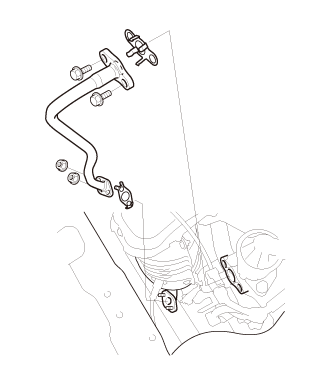
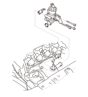
| 12. | Thermostat Housing |
|
|
|
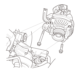
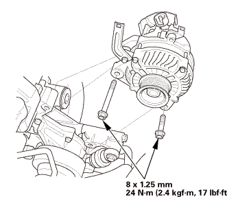
| 13. | Alternator |
|
|
|
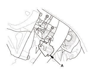
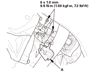
| 14. | Lower Torque Rod Bracket (M/T) |
|
|
|
| 15. | Lower Torque Rod Bracket (A/T) |
|
|
|
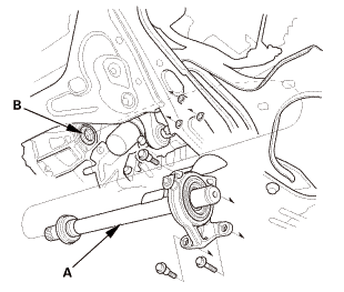
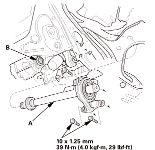
| 16. | Intermediate Shaft Assembly |
|
|
|
|
|
|
||||||
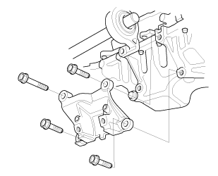
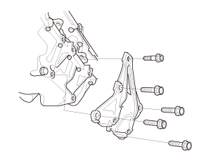
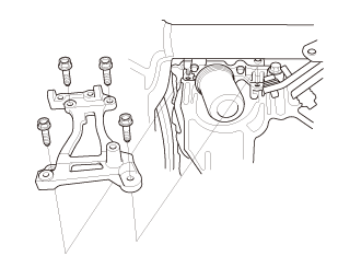
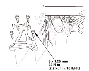
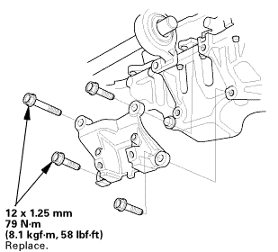
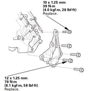
| 17. | A/C Compressor Bracket |
|
|
|
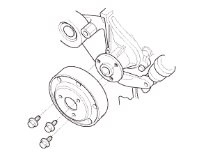
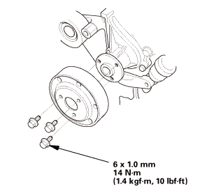
| 18. | Water Pump Pulley |
|
|
|
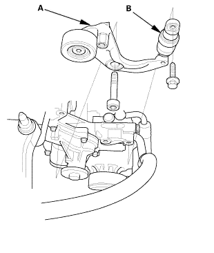
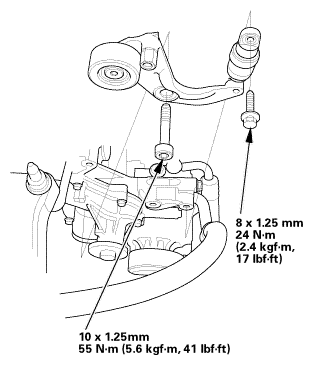
| 19. | Auto Tensioner Assembly |
|
|
|
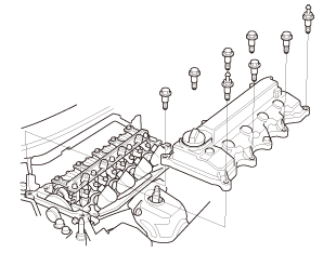
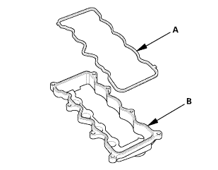
| 20. | Cylinder Head Cover and/or Packing |
|
|
|
|
|
|
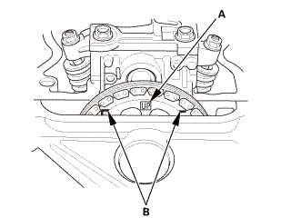
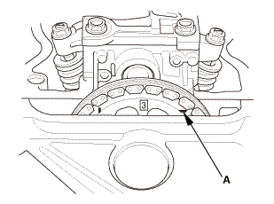
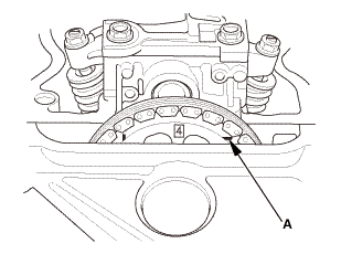
| 21. | Check The No.1 Piston at Top Dead Center (With Cam Chain Case/Oil Pump) |
|
|
|
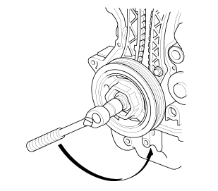
| 22. | Crankshaft Pulley |
|
|
|
 [av
[av| 23. | Engine Oil Pump Assembly |
|
|
|
|
|
|
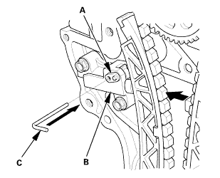
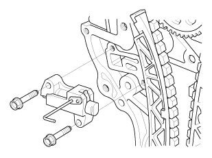
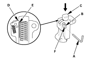
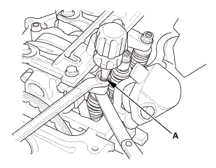
| 24. | Cam Chain Auto-Tensioner |
|
|
|
||||||||||||
|
|
|
|
|
|
||||||||||||
|
|
|
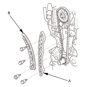
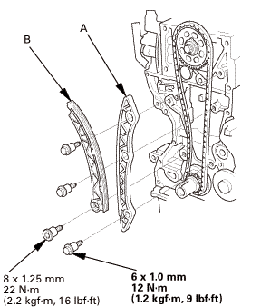
| 25. | Cam Chain |
|
|
|
| 26. | Cylinder Head Assembly |
|
|
|
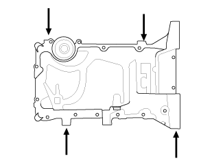
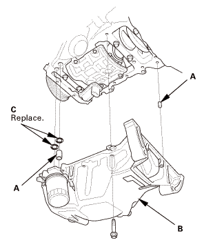
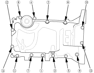
| 27. | Oil Pan Assembly |
|
|
|
|
|
|
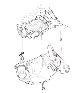
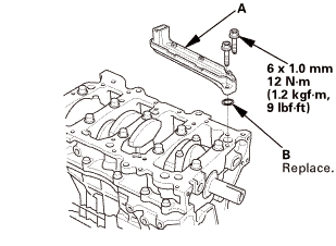
| 28. | Engine Oil Strainer |
|
|
|
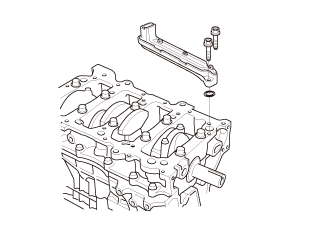
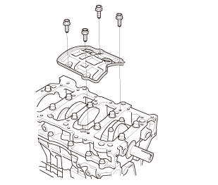
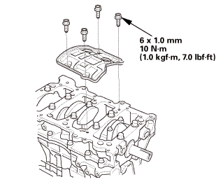
| 29. | Engine Baffle Plate |
|
|
|
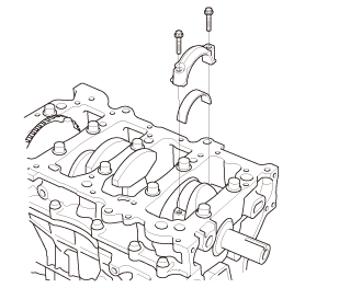
| 30. | Connecting Rod Cap and The Bearing Half |
|
|
|

Installation
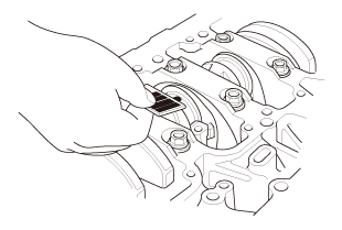
| 1. | Connecting Rod Bearing Clearance Inspection |
|
|
|
|||||||||||||||||||||||||||||||||||||||||||

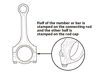
| 2. | Connecting Rod Bearing Selection |
|
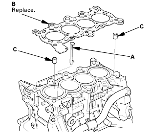
1. |
Inspect each connecting rod for cracks and heat damage. |
 redandrunisind
|
2. |
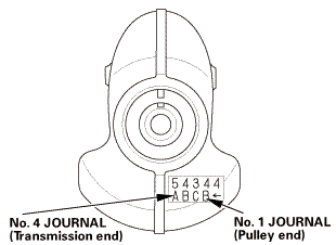
Each connecting rod has a tolerance range from 0 to 0.024 mm (0.00094 in), in 0.006 mm (0.00024 in) increments, depending on the size of its big end bore. It's then stamped with a number or bar (1, 2, 3, or 4/l, ll, lll, or llll) indicating the range. You may find any combination of numbers and bars in any engine. (Half the number or bar is stamped on the rod cap, the other half is on the connecting rod.) If you cannot read the code because of an accumulation of oil and varnish, do not scrub it with a wire brush or scraper. Clean it only with solvent or detergent. |
|||||
|
||||||
|
|
|
 (pulley
|
|
|
|||||||||||||||||
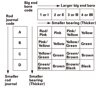 a.ndendam,amznvllred/pink/pinkvellawpink/emwnbrawnsmnllevmd
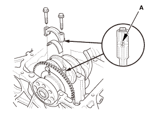
| 3. | Connecting Rod Cap and The Bearing Half |
|
|
|
|
|
|
|||||||||
| 4. | Engine Baffle Plate |
|
|
|
| 5. | Engine Oil Strainer |
|
|
|
| 6. | Oil Pan Assembly |
|
|
|
|||||||||||||||||||||||
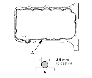 mm
mm|
|
|
|
|
|
|||||||||||||||||
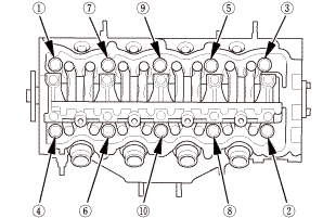
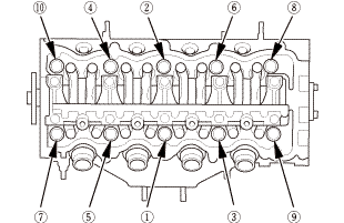
| 7. | Cylinder Head Assembly |
|
|
|
|
|
|
 inmmam
|
|
|
|
|
|
||||||
 secounstep
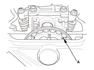
| 8. | Set The No.1 Piston at Top Dead Center (Without Cam Chain Case/Oil Pump) |
|
|
|
| 9. | Cam Chain |
|
|
|
|
|
|
|
|
|
 ...,is(1.2
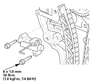
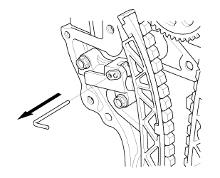
| 10. | Cam Chain Auto-Tensioner |
|
|
|
||||||
|
|
|
 nokvf-in.
|
|
|
| 11. | Engine Oil Pump Assembly |
|
|
|
||||||||||||||||||||||||||
|
|
|
||||||||||||||
|
|
|
||||||||||||||||||||||||||||||
 25mm(7(32k1n1omm12
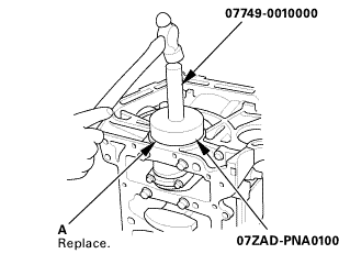
| 12. | Crankshaft Oil Seal, Transmission side |
|
|
|
|
|
|
||||||||||
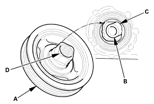
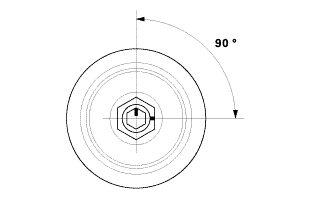
| 13. | Crankshaft Pulley |
|
|
|
|
|
|
|
|
|
|||||||||||||
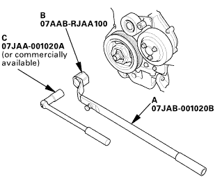 o7jaanmo2oa
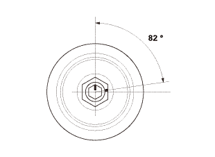
|
|
|
||||||||||
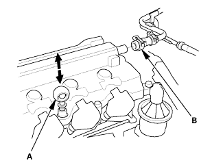
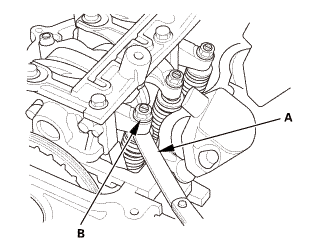
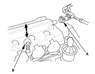
| 14. | Valve Clearance Adjustment |
|
|
|

|
2. |
Select the correct feeler gauge for the valve clearance you are going to check. |
|||||||||
|
||||||||||
 no!
no!
|
|
|
|
|
|
|||||||||||||||
|
|
|
|
|
|
|
|
|
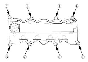
| 15. | Cylinder Head Cover and/or Packing |
|
|
|
|||||||||||||||
|
|
|
||||||||||||||||||||
|
|
|
||||||||||||||||||||
|
|
|
| 16. | Auto Tensioner Assembly |
|
|
|
 inl.25mmssn-m
| 17. | Water Pump Pulley |
|
|
|
| 18. | A/C Compressor Bracket |
|
|
|
| 19. | Intermediate Shaft Assembly |
|
|
|
||||||
 inmmn-mu.o
|
|
|
 mms.
mms.| 20. | Lower Torque Rod Bracket (M/T) |
|
|
|
 mm
mm| 21. | Lower Torque Rod Bracket (A/T) |
|
|
|
 u.z5mm75n-mmm
| 22. | Alternator |
|
|
|
| 23. | Thermostat Housing |
|
|
|
 11
11| 24. | Catalytic Converter and EGR Pipe Assembly |
|
|
|
 num(2.2m.2:m41!
|
|
|
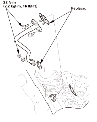 22n-m
22n-m| 25. | Exhaust Chamber Cover |
|
|
|
| 26. | A/F Sensor (Sensor 1) |
|
|
|
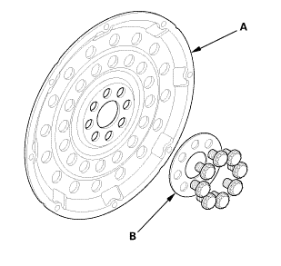
| 27. | Drive Plate Assembly |
|
|
|
 55
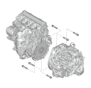
55| 28. | Automatic Transmission Assembly (A/T) |
|
|
|
 usmmn-mlbml)
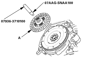
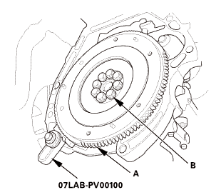
| 29. | Flywheel |
|
|
|
|
|
|
 :2minn-inno
| 30. | Clutch Disc |
|
|
|
||||||||||||
 (pm
(pm| 31. | Pressure Plate |
|
|
|
|
|
|
|||||||||||||||||||||||||||||||||
 a7aag-suaa1aa
| 32. | Manual Transmission Assembly (M/T) |
|
|
|
| 33. | Engine Wire Harness |
|
|
|
| 34. | Intake Manifold and Throttle Body Assembly |
|
|
|
|
|
|
|
|
|

|
|
|
|
|
|
 Piston, Ring, Pin, and Connecting Rod Removal and Installation (R18Z1)
Removal
1.
Intake Manifold and Throttle Body Assembly
1.
Remove the intake air duct.
...
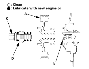
 Connecting Rod Bolt Inspection (Except K24Z7)
Inspection
1.
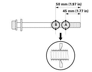
Connecting Rod Bolt - Inspection
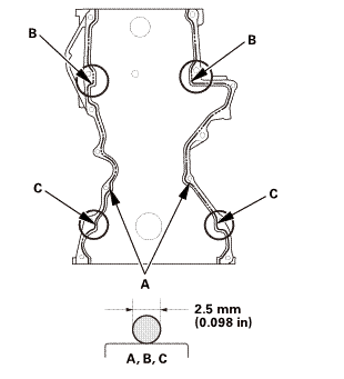
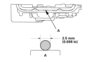
1.
Measure the diameter of each connecting rod bolt at point A and point
B.
:5mmzommin)
...
See also:
Honda Civic Owners Manual. Inspecting and Changing Fuses
Turn the ignition switch to LOCK 0*1. Turn
headlights and all accessories off.
Remove the fuse box cover.
Check the large fuse in the engine
compartment.
► If the fuse is blown, use a Phillips-head
screwdriver to remove the screw and
replace it with a new one.
...
