Honda Civic Service Manual: Connecting Rod and Crankshaft End Play Inspection (R18A9)

Removal
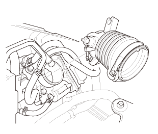
| 1. | Intake Manifold and Throttle Body Assembly (Natural Gas Model) |
|
|
|
|
|
|
|
|
|

|
|
|
|
|
|
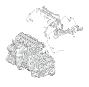
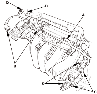
| 2. | Engine Wire Harness |
|
|
|
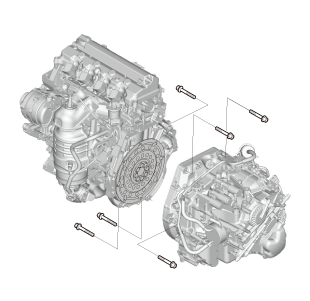
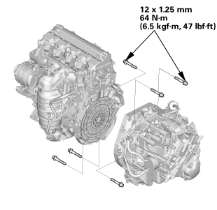
| 3. | Automatic Transmission Assembly (A/T) |
|
|
|
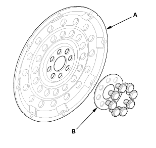
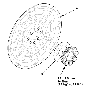
| 4. | Drive Plate Assembly |
|
|
|
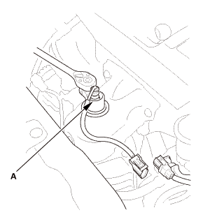
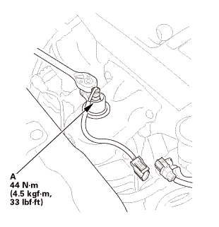
| 5. | A/F Sensor (Sensor 1) |
|
|
|
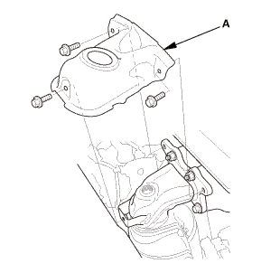
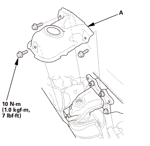
| 6. | Exhaust Chamber Cover (Natural Gas Model) |
|
|
|
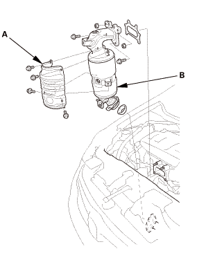
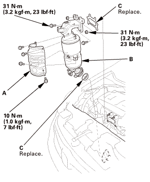
| 7. | Catalytic Converter (Natural Gas Model) |
|
|
|
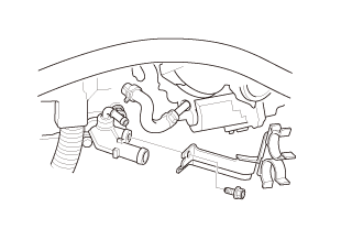
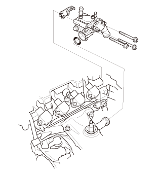
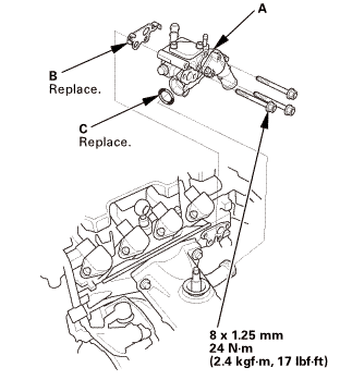
| 8. | Thermostat Housing (Natural Gas Model) |
|
|
|
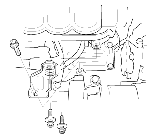
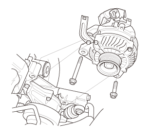
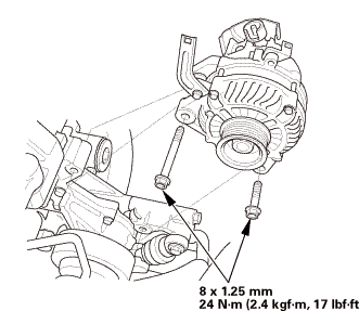
| 9. | Alternator |
|
|
|
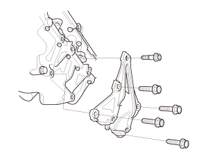
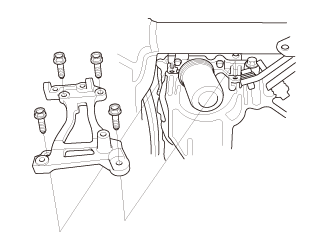
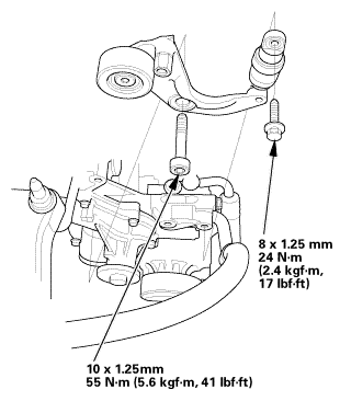
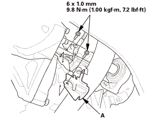
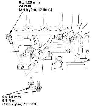
| 10. | Lower Torque Rod Bracket (A/T) |
|
|
|
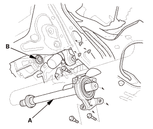
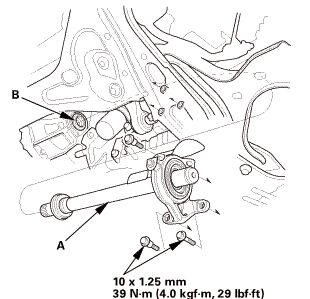
| 11. | Intermediate Shaft Assembly |
|
|
|
|
|
|
||||||
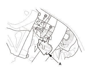
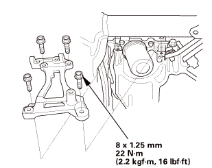
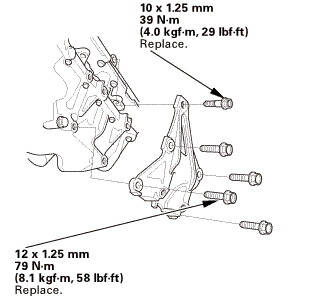
| 12. | A/C Compressor Bracket |
|
|
|
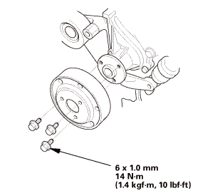
| 13. | Water Pump Pulley |
|
|
|
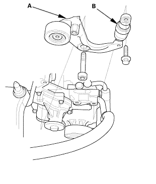
| 14. | Auto Tensioner Assembly |
|
|
|
| 15. | Cylinder Head Cover and/or Packing |
|
|
|
|
|
|
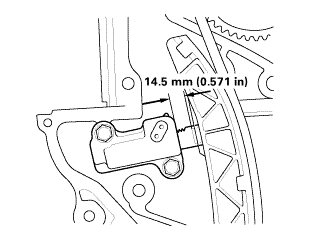
| 16. | Check The No.1 Piston at Top Dead Center (With Cam Chain Case/Oil Pump) |
|
|
|
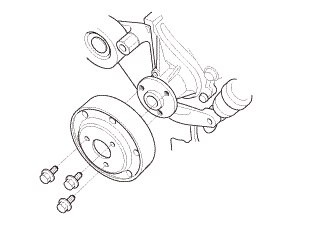
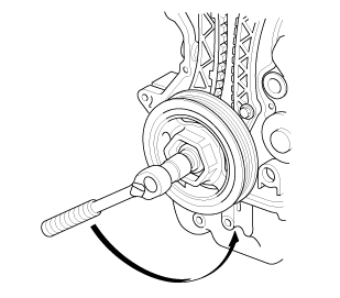
| 17. | Crankshaft Pulley |
|
|
|
 [av
[av| 18. | Engine Oil Pump Assembly |
|
|
|
|
|
|
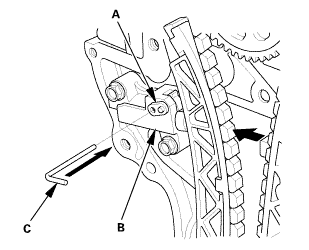
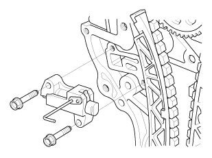
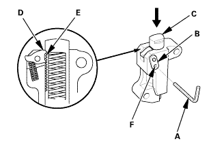
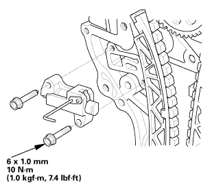
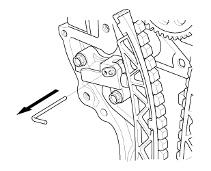
| 19. | Cam Chain Auto-Tensioner |
|
|
|
||||||||||||
|
|
|
|
|
|
||||||||||||
|
|
|
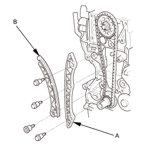
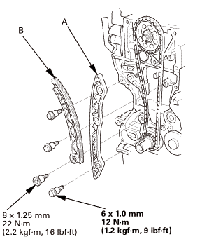
| 20. | Cam Chain |
|
|
|
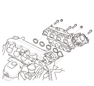
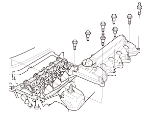
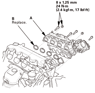
| 21. | Cylinder Head Assembly |
|
|
|
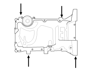
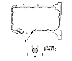
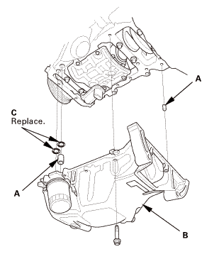
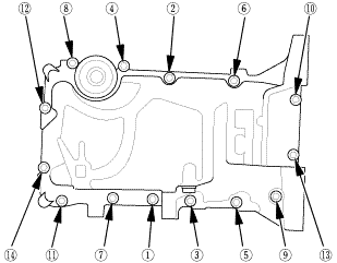
| 22. | Oil Pan Assembly |
|
|
|
|
|
|
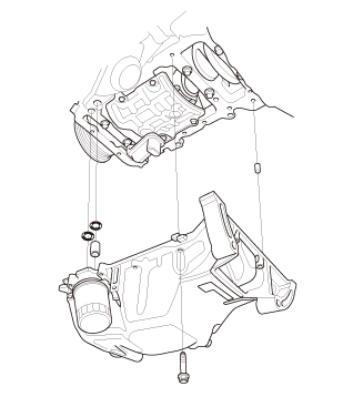
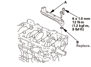
| 23. | Engine Oil Strainer |
|
|
|
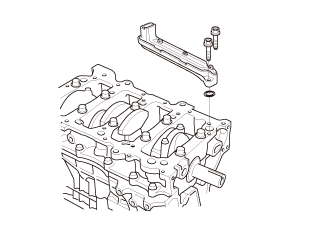
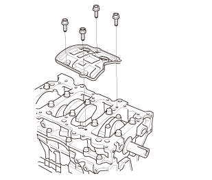
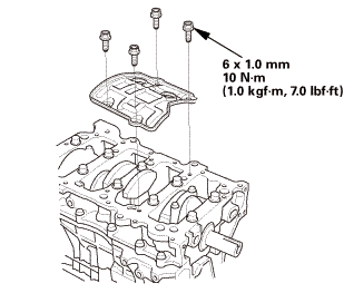
| 24. | Engine Baffle Plate |
|
|
|
 Inspection
| 1. | Connecting Rod and Crankshaft End Play - Inspection |
|
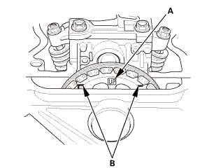
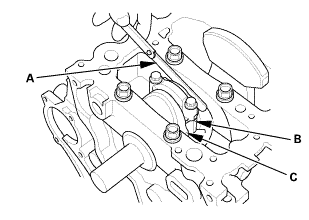
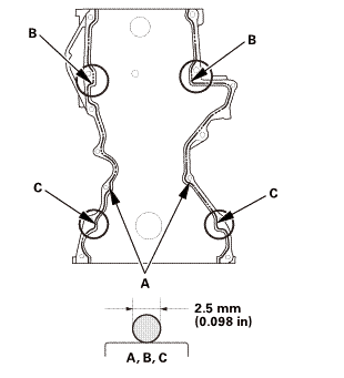
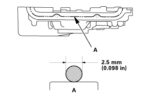
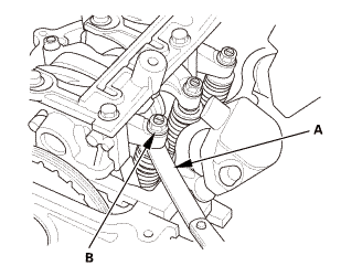
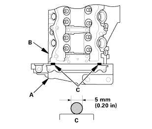
1. |
Measure the connecting rod end play with a feeler gauge (A) between the connecting rod (B) and the crankshaft (C). |
|||||||||
|
||||||||||
|
2. |
If the connecting rod end play is beyond the service limit, install a new connecting rod, and recheck. If it is still beyond the service limit; replace the crankshaft. |
|
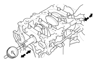
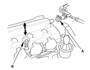
3. |
Push the crankshaft firmly away from the dial indicator by prying, and zero the dial against the end of the crankshaft. Then pull the crankshaft firmly back toward the indicator by prying; the dial reading should not exceed the service limit. |
|||||||||
|
||||||||||
|
4. |
If the crankshaft end play is beyond the service limit, replace the thrust washers and recheck. If it is still beyond the service limit, replace the crankshaft. |

Installation
| 1. | Engine Baffle Plate |
|
|
|
| 2. | Engine Oil Strainer |
|
|
|
| 3. | Oil Pan Assembly |
|
|
|
|||||||||||||||||||||||
 mm
mm
|
|
|
|
|
|
|||||||||||||||||
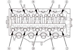
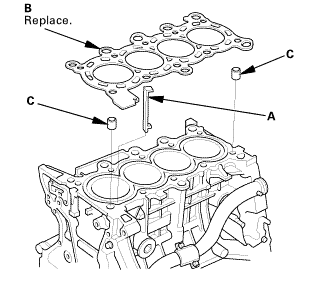
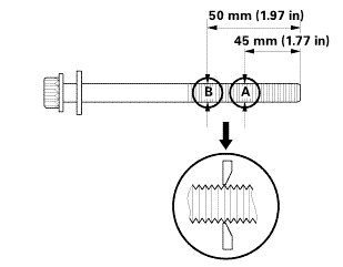
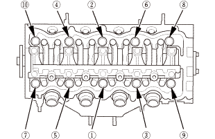
| 4. | Cylinder Head Assembly |
|
|
|
|
|
|
 inmmam
|
|
|
|
|
|
||||||
 secounstep
| 5. | Set The No.1 Piston at Top Dead Center (Without Cam Chain Case/Oil Pump) |
|
|
|
| 6. | Cam Chain |
|
|
|
|
|
|
|
|
|
 ...,is(1.2
| 7. | Cam Chain Auto-Tensioner |
|
|
|
||||||
|
|
|
 nokvf-in.
|
|
|
| 8. | Engine Oil Pump Assembly |
|
|
|
||||||||||||||||||||||||||
|
|
|
||||||||||||||
|
|
|
||||||||||||||||||||||||||||||
 25mm(7(32k1n1omm12
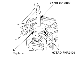
| 9. | Crankshaft Oil Seal, Transmission side |
|
|
|
|
|
|
||||||||||
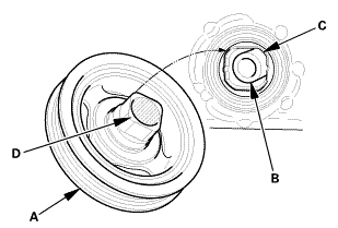
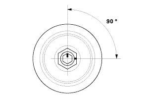
| 10. | Crankshaft Pulley |
|
|
|
|
|
|
|
|
|
|||||||||||||
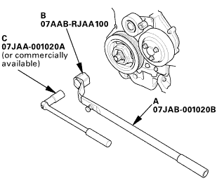 o7jaanmo2oa
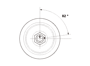
|
|
|
||||||||||
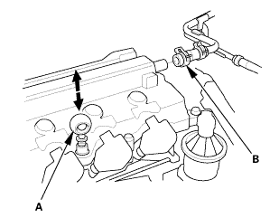
| 11. | Valve Clearance Adjustment |
|
|
|

|
2. |
Select the correct feeler gauge for the valve clearance you are going to check. |
|||||||||
|
||||||||||
 no!
no!
|
|
|
|
|
|
|||||||||||||||
|
|
|
|
|
|
|
|
|
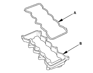
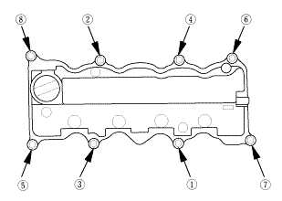
| 12. | Cylinder Head Cover and/or Packing |
|
|
|
|||||||||||||||
|
|
|
||||||||||||||||||||
|
|
|
||||||||||||||||||||
|
|
|
| 13. | Auto Tensioner Assembly |
|
|
|
 inl.25mmssn-m
| 14. | Water Pump Pulley |
|
|
|
| 15. | A/C Compressor Bracket |
|
|
|
| 16. | Intermediate Shaft Assembly |
|
|
|
||||||
 inmmn-mu.o
|
|
|
 mms.
mms.| 17. | Lower Torque Rod Bracket (A/T) |
|
|
|
 u.z5mm75n-mmm
| 18. | Alternator |
|
|
|
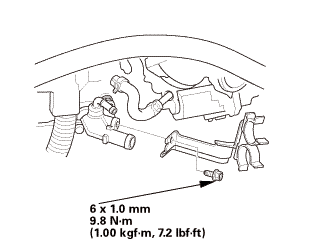
| 19. | Thermostat Housing (Natural Gas Model) |
|
|
|
 imm
imm| 20. | Catalytic Converter (Natural Gas Model) |
|
|
|
 :1mm.....
| 21. | Exhaust Chamber Cover (Natural Gas Model) |
|
|
|
| 22. | A/F Sensor (Sensor 1) |
|
|
|
| 23. | Drive Plate Assembly |
|
|
|
 55
55| 24. | Automatic Transmission Assembly (A/T) |
|
|
|
 usmmn-mlbml)
| 25. | Engine Wire Harness |
|
|
|
| 26. | Intake Manifold and Throttle Body Assembly (Natural Gas Model) |
|
|
|
|
|
|
|
|
|
|
|
|
|
|
|
 Connecting Rod and Crankshaft End Play Inspection (K24Z7)
Removal
1.
Engine Wire Harness
1.
Remove the engine wire harness.
2.
Intermed ...
 Crankshaft Pilot Bushing Inspection (K24Z7)
Removal
1.
Pressure Plate
1.
Install the ring gear holder.
2.
...
See also:
Honda Civic Owners Manual. Agile Handling Assist
Lightly brakes selective wheels, as needed, when you turn the steering wheel,
and
helps support the vehicle's stability and performance during cornering.
Agile Handling Assist
The agile handling assist cannot enhance stability in
all driving situations. You still need to drive a ...
