Honda Civic Service Manual: Automatic Transmission Removal and Installation (A/T)
218102

|
NOTE: |
|
|||
|

| 1. | Vehicle Lift |
|
| 2. | Wide - Hood Open Position |
|
|
|
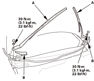
| 3. | Wiper Arm Assembly |
|
|
|
| 4. | Both Side Cowl Covers |
|
|
|
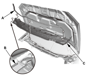
| 5. | Center Cowl Cover |
|
|
|

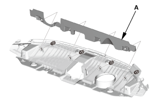
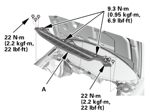
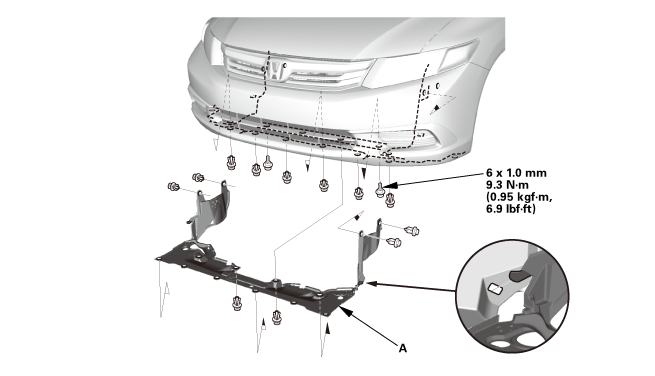
| 6. | Under Cowl Panel |
|
|
|
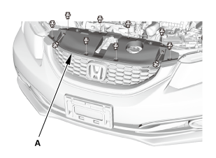
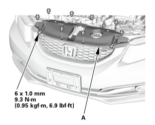
| 7. | Front Grille Cover |
|
|
|
|
|
|
| 8. | Battery Terminal - Disconnection |
|
|
|
|||||||||||||||||||||||||||
| 9. | Intake Air Pipe |
|
|
|
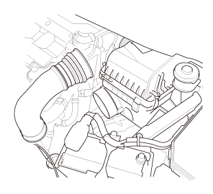
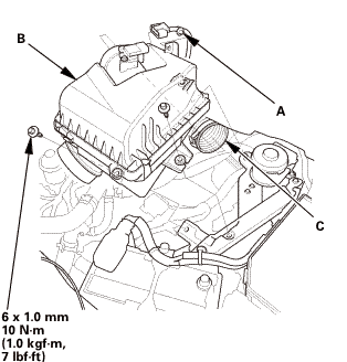
| 10. | Air Cleaner |
|
|
|
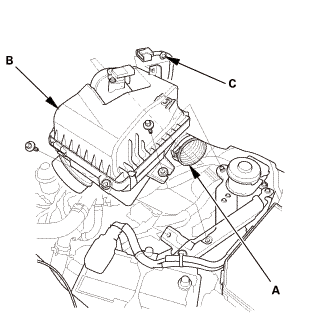
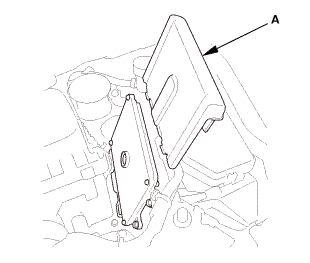
| 11. | ECM/PCM |
|
|
|
|
|
|
|||||||||
| 12. | Air Cleaner Bracket |
|
|
|
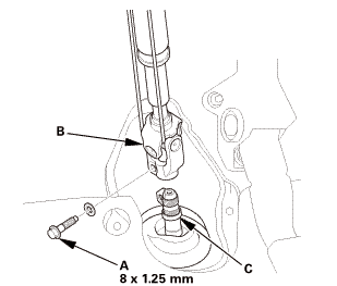
| 13. | Steering Joint Cover |
|
|
|
| 14. | Steering Column Lower Slide Shaft - Hold |
|
|
|
| 15. | Steering Joint Bolt - Loosen |
|
|
|
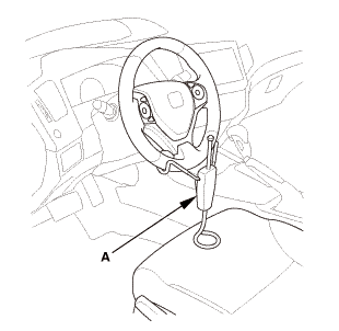
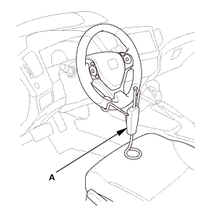
| 16. | Steering Wheel Hold |
|
|
|
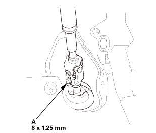
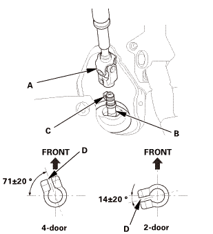
| 17. | Steering Joint - Disconnection |
|
|
|
||||||||||||||||||||
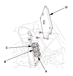
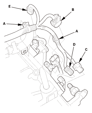
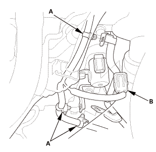
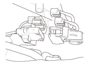
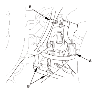
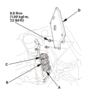
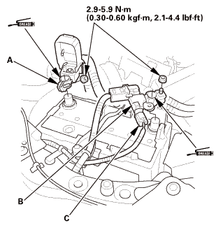
| 18. | A/T Clutch Pressure Control Solenoid Valve Harness - Disconnection |
|
|
|
||||||||||||||||||||||||
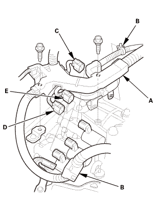
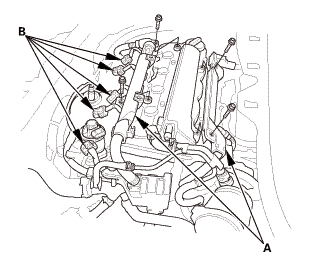
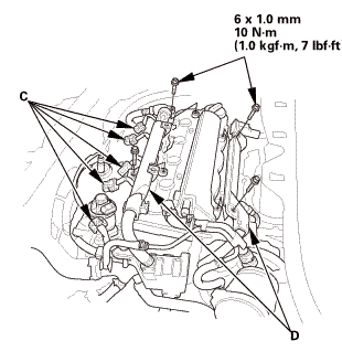
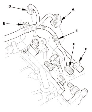
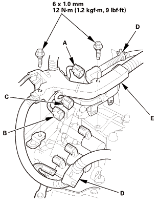
| 19. | Automatic Transmission Peripheral Assembly, Upper Side |
|
|
|
|||||||||||||||||||||||||
|
|
|
|
|
|
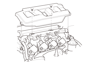
| 20. | Engine Cover |
|
|
|
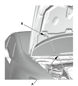
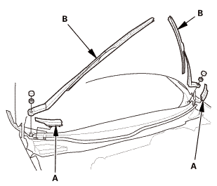
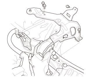
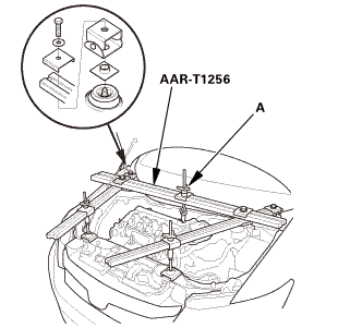
| 21. | Engine Support Hanger Peripheral Assembly |
|
|
|
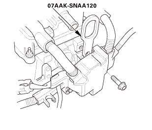
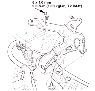
| 22. | Engine Support Hanger |
|
|
|
|
|
|
||||||||||||
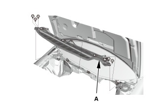
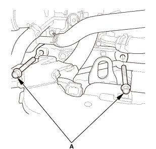
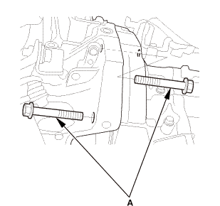
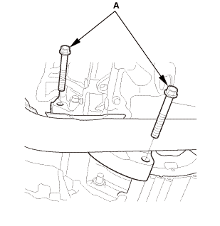
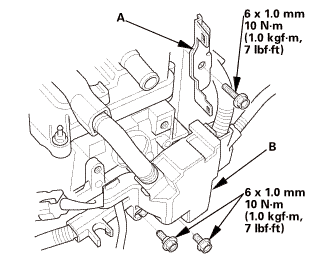
| 23. | Upper Transmission Assembly Mounting Bolt |
|
|
|
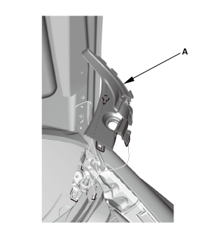
| 24. | Transmission Mount |
|
|
|
|||||||||
| 25. | Raise The Vehicle On The Lift |
|
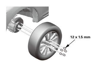
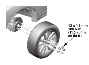
| 26. | Front Wheel |
|
|
|
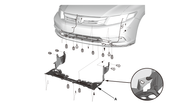
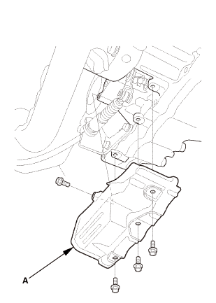
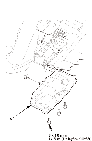
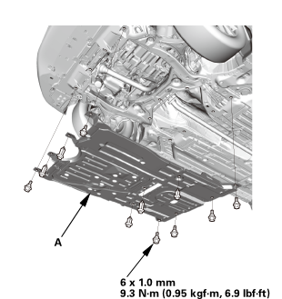
| 27. | Splash Shield |
|
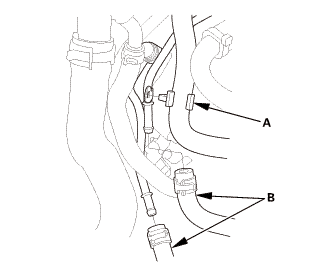
1. |
Remove the splash shield (A). |
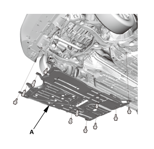
| 28. | Engine Undercover |
|
|
|
| 29. | ATF - Replacement |
|
|
|
 (somn)
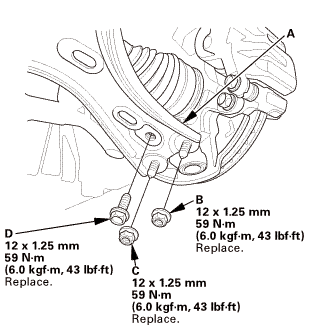
| 30. | Lower Arm Joint - Disconnection, Both Knuckle Side |
|
|
|
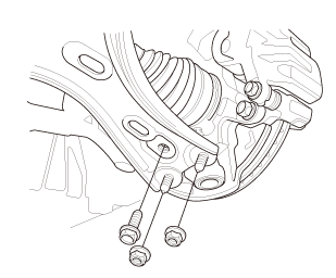
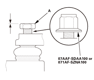
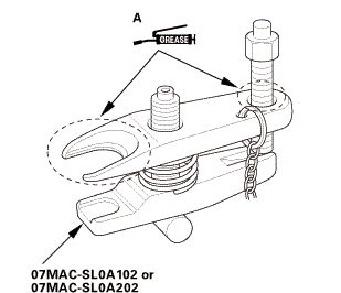
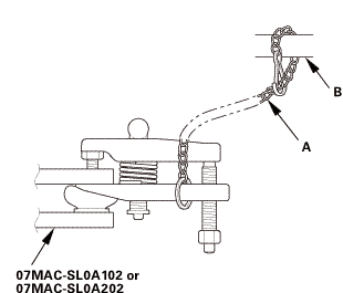
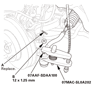
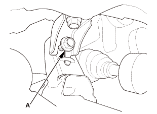
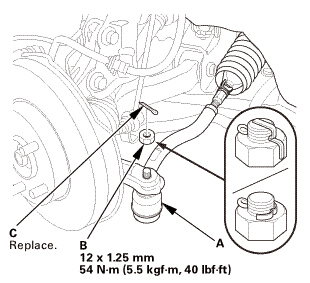
| 31. | Ball Joint - Removal |
|
|
Always use a ball joint remover to disconnect a ball joint. Do not strike the housing or any other part of the ball joint connection to disconnect it.
|
||||||

|
|
|
 ov
ov|
|
|
||||||||||||||||||||||||||||||||
 wmae-sldaidz
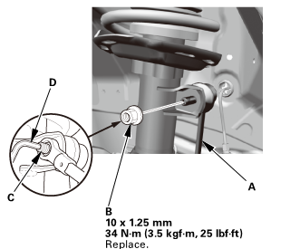
| 32. | Tie-Rod End Ball Joint - Disconnection, Both Side |
|
|
|
||||||||||||
 n7aaf-sdaainnmm
| 33. | Front Stabilizer Ball Joint, Both Damper Side - Disconnection |
|
|
|
| 34. | Lower Torque Rod - Disconnection |
|
|
|
| 35. | Subframe Support |
|
|
|
| 36. | Front Subframe Assembly |
|
|
|
|
|
|
|
|
|
| 37. | Transmission Jack Support |
|
| 38. | A/T Peripheral Assembly, Lower Side |
|
|
|
|||||||||||||||||
|
|
|
| 39. | Torque Converter - Disconnection |
|
|
|
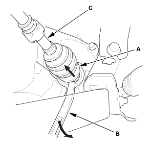
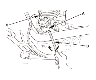
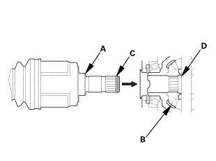
| 40. | Driveshaft Front Both, Inboard Side - Disconnection |
|
Left side
Right side
|
|
|||||||||||||||||
|
|
|
| 41. | Shift Cable Cover |
|
|
|
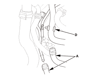
| 42. | Shift Cable - Disconnection A/T Side |
|
|
|
|||||||||||||||
| 43. | A/T Assembly |
|
Front side
Rear side
|
|
|||||||||||||||
| 44. | Torque Converter |
|
|
|

| 1. | Torque Converter |
|
|
|
|||||||||
| 2. | A/T Assembly |
|
Front side
Rear side
|
|
 u.z5mm
| 3. | Shift Cable, A/T Side - Reconnection |
|
|
|
|||||||||||||||
 ......u....(nas
| 4. | Shift Cable Cover |
|
|
|
 mm:12
mm:12| 5. | Driveshaft Front Both, Inboard Side - Reconnection |
|
|
|
|
|
|
||||||||||||
| 6. | Torque Converter - Reconnection |
|
|
|
| 7. | A/T Peripheral Assembly, Lower Side |
|
|
|
 mmml2.1m.10mm
|
|
|
|||||||||||||||||
| 8. | Subframe Support |
|
|
|
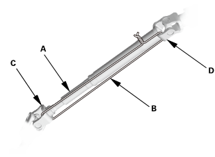
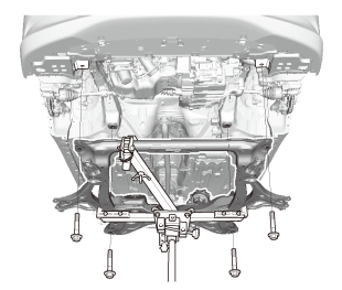
| 9. | Front Subframe Assembly |
|
1. |
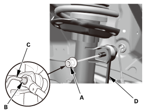
Loosely install the new front subframe mounting bolts (A). |
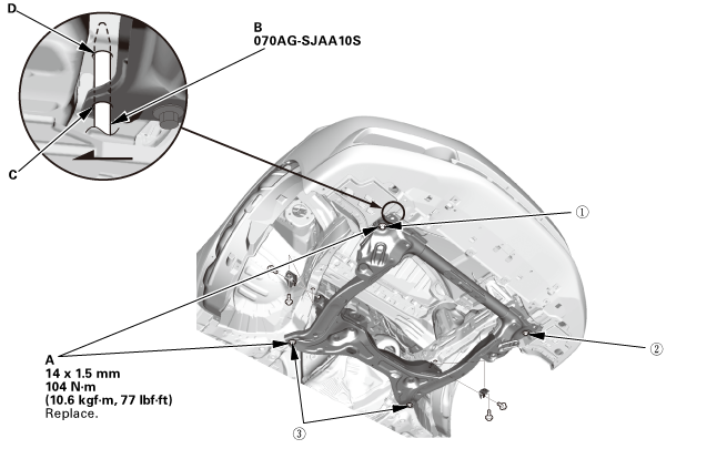 o7oagsjaaosn-m77lm41!
|
2. |
Insert the subframe alignment pin (B) through the positioning hole (C) on the right front subframe, and into the positioning hole (D) on the body, then loosely tighten the subframe right front mounting bolt. |
|
3. |
Insert the subframe alignment pin through the positioning slot on the left front subframe, and into the positioning hole on the body, then loosely tighten the subframe left front mounting bolt. |
|
4. |
Tighten the subframe mounting bolts to the specified torque values starting with the right front subframe mounting bolt. Use the subframe alignment pin when tightening the front side subframe mounting bolts. |
|
5. |
Check all of the subframe mounting bolts, and retighten if necessary. |
|
|
NOTE: Tighten the bolts in the sequence shown. |
||
|
6. |
Remove the transmission jack and the subframe adapter. |
|
|
|
|
|
|
| 10. | Lower Torque Rod - Reconnection |
|
|
|
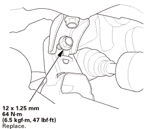
| 11. | Front Stabilizer Ball Joint, Both Damper Side - Reconnection |
|
|
|
 125mmmm
| 12. | Tie-Rod End Ball Joint - Connection, Both Side |
|
|
|
|||||||||||||||
| 13. | Lower Arm Joint - Reconnection, Both Knuckle Side |
|
|
|
 mm
mm| 14. | Lower The Vehicle On The Lift |
|
| 15. | Upper Transmission Assembly Mounting Bolt |
|
|
|

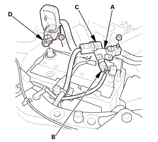
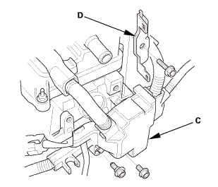
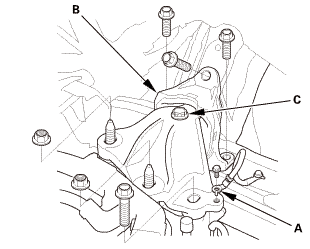
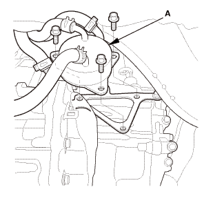
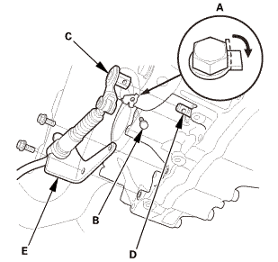
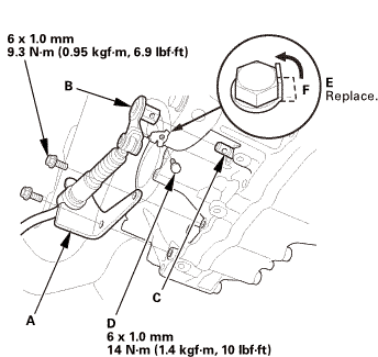
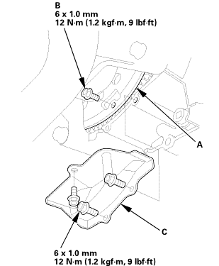
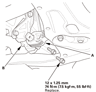
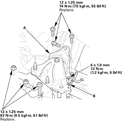
| 16. | Transmission Mount |
|
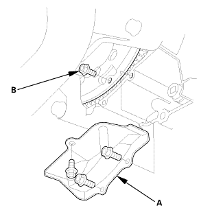
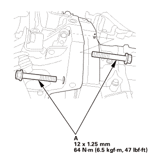
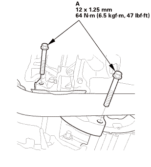
1. |
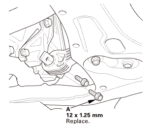
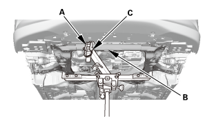
Install the transmission mount assembly (A) using new bolts and new nuts. |
 mmm,55mm121.25mmu....51
|
2. |
Install the ground cable terminal (B). |
| 17. | Engine Support Hanger |
|
|
|
| 18. | Engine Support Hanger Peripheral Assembly |
|
|
|
| 19. | Engine Cover |
|
|
|
| 20. | Automatic Transmission Peripheral Assembly, Upper Side |
|
|
|
|
|
|
|
|
|
|||||||||||||||||||||||||
| 21. | A/T Clutch Pressure Control Solenoid Valve Harness - Reconnection |
|
|
|
||||||||||||||||||||||||
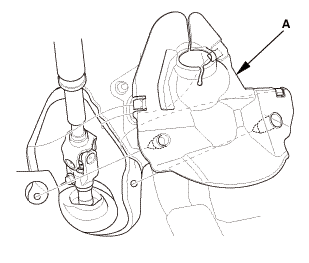
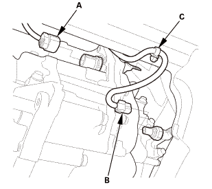
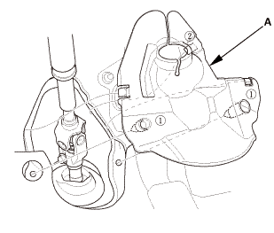
| 22. | ATF - Replacement |
|
|
|
|
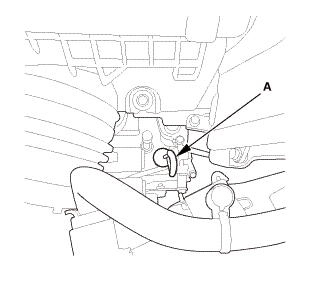
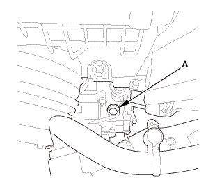
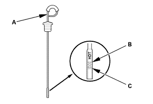
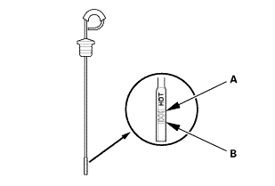
2. |
Refill the transmission with the recommended fluid into the dipstick hole (A) to bring the fluid level between the upper mark and the lower mark of the dipstick. Always use Honda automatic transmission fluid (ATF) ATF DW-1. Using a non-Honda ATF can affect shift quality. |
|||||||||
|
||||||||||
|
|
|
| 23. | Steering Column Lower Slide Shaft - Release |
|
|
|
| 24. | Steering Wheel Release |
|
|
|
| 25. | Steering Joint - Reconnection |
|
|
|
||||||||||||||||||||
|
|
|
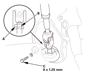
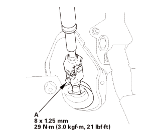
| 26. | Steering Joint Bolt - Tighten |
|
|
|
 mm:.o21
| 27. | Steering Joint Cover |
|
|
|
| 28. | Air Cleaner Bracket |
|
|
|
 in
in| 29. | ECM/PCM |
|
|
|
|||||||||
|
|
|
| 30. | Air Cleaner |
|
|
|
| 31. | Intake Air Pipe |
|
|
|
| 32. | Battery Terminal - Reconnection |
|
|
|
|||||||||||||||||||
| 33. | Front Grille Cover |
|
|
|
|
|
|
| 34. | Under Cowl Panel |
|
|
|
 22mm)2222
| 35. | Center Cowl Cover |
|
|
|
| 36. | Both Side Cowl Covers |
|
|
|
| 37. | Wiper Arm Assembly |
|
|
|
 1.122
1.122| 38. | Raise The Vehicle On The Lift |
|
| 39. | Engine Undercover |
|
|
|
 1.0mmmm
| 40. | Splash Shield |
|
1. |
Install the splash shield (A). |
| 41. | Front Wheel |
|
|
|
||||||
 mmmln-mnomm
| 42. | A/T After Install Check |
|
| 43. | Pre-Alignment Checks |
|
| 44. | Caster - Inspection |
|
|||||||||||||||||||||||||||||||||||||||||||||||
| 45. | Camber - Inspection |
|
||||||||||||||||||||||||||||||||||||||||||||||||||||||||||||||||||||||||||||||||||||||
| 46. | Front Toe - Inspection |
|
|||||||||||||||||||||||||
| 47. | Turning Angle - Inspection |
|
|
|
|||||||||||||||||||||||||||||||||||||||||||||||||||||||||||||||||||||||||||||||||||||||||
|
|
|
|||||||||||||||||||||||||||||||||||||||||||||||||||||||||
| 48. | Warm Up The Engine |
|
| 49. | ATF Level Check |
|
|
|
|
|
|
||||||||||||||||||||||||||||||||||
|
|
|
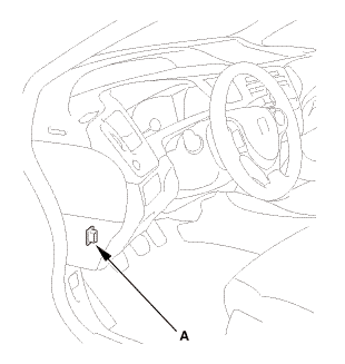
| 50. | HDS DLC - Connection |
|
|
|
| 51. | Automatic Transmission Road - Test |
|
1. |
Park the vehicle on the level ground. |
|
2. |
Apply the parking brake, and block all four wheels. |
|
3. |
Start the engine. |
|
4. |
Shift to D while pressing the brake pedal. Press the accelerator pedal, and release it suddenly. The engine should not stall. |
|
5. |
Repeat step 4 in all shift lever positions. |
|
6. |
Prepare the HDS and the MVCI to take a SNAPSHOT (refer to the HDS user's guide for more details if needed): |
|
7. |
Find a suitable level road. |
|
8. |
When you are ready to do the test, press OK on the HDS. |
|
9. |
Accelerate quickly until APP Sensor A reads 1.3 V. Maintain a steady throttle until the transmission shifts to 5th gear, then slow the vehicle and come to a stop. |
|
10. |
Save the snapshot if the entire event was recorded or increase the recording time setting as necessary, and repeat step 9. |
|
11. |
Adjust the parameter setting to 2.4 V. |
|
12. |
Test-drive the vehicle again. Accelerate quickly until APP Sensor A reads 2.5 V. Maintain a steady throttle until the transmission shifts to 5th gear (or a reasonable speed), then slow the vehicle and come to a stop. |
|
13. |
Save the snapshot if the entire event was recorded or increase the recording time setting as necessary, and repeat step 12. |
|
14. |
Accelerate quickly until the accelerator pedal is to the floor. Maintain a steady pedal until the transmission shifts to 3rd gear, then slow to a stop, and save the snapshot. |
|
15. |
Review each snapshot individually, and compare the Shift Control, APP Sensor A (V), and the Vehicle Speed to the following table. |
|||||||||||||||||||||||||||||||||||
|
Upshift: D Position
|
||||||||||||||||||||||||||||||||||||
|
Downshift: D Position
|
||||||||||||||||||||||||||||||||||||
|
16. |
Drive the vehicle in 4th or 5th gear, then shift to 2nd gear. The vehicle should immediately begin to slow down from engine braking. |
|
17. |
Shift to 1, accelerate from a stop at full throttle, and check for abnormal noise and clutch slippage. Upshifts should not occur in this position. |
|
18. |
Shift to 2, accelerate from a stop at full throttle, and check for abnormal noise and clutch slippage. Upshifts and downshifts should not occur in this position. |
|
19. |
Shift to R, accelerate from a stop at to full throttle momentarily, and check for abnormal noise and clutch slippage. |
|
20. |
Park the vehicle on an upward slope (about 16 degrees), apply the parking brake, and shift into P. Release the brake; the vehicle should not move. |
|
|
NOTE: Always use the parking brake to hold the vehicle when stopped on an incline in gear. Depending on the grade of the incline, the vehicle could roll if the brake is released. |
||
| 52. | VSA Sensor Neutral Position - Memorization |
|
||||||||||
| 53. | Steering Angle Sensor Neutral Position - Clear |
|
|||||||
| 54. | Maintenance Minder Reset |
|
 Automatic Transmission End Crankshaft Oil Seal Replacement - In Car (A/T)
1111M2 TRANSMISSION SIDE
Removal
1.
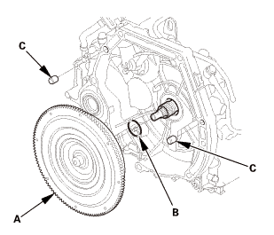
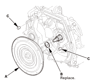
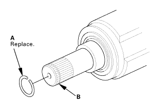
Drive Plate Assembly
1.
Remove the drive plate (A) and the washer (B).
...
 Carpet Removal and Installation (2-door A/T)
847100
SRS components are located in this area. Review the SRS component locations
and the precautions and procedures before doing repairs or service.
1.
Batt ...
See also:
Honda Civic Owners Manual. TPMS and the Compact Spare Tire
U.S. models
If you replace a flat tire with the spare tire, the low tire pressure/TPMS
indicator
comes on while you are driving. After driving for a few miles (kilometers), the
indicator will start blinking for a short time and then stay on. Tire Pressures
Low
appears on the driver informati ...
