Honda Civic Service Manual: Audio Remote/Multi-Information Display Switch Removal, Installation, and Test
7461E1

Removal
|
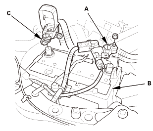
SRS components are located in this area. Review the SRS component locations and the precautions and procedures before doing repairs or service. |
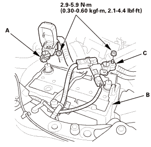
| 1. | Battery Terminal (SRS) - Disconnection |
|
|
|
|||||||||||||||
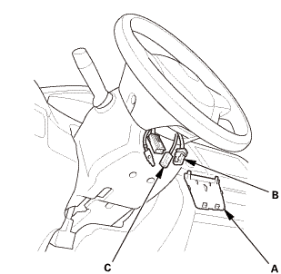
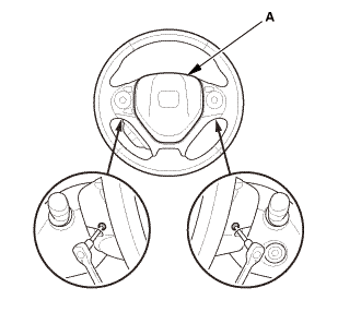
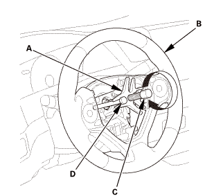
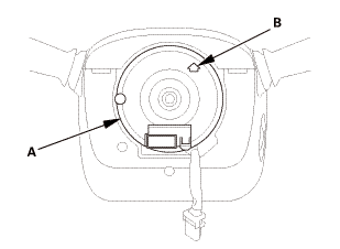
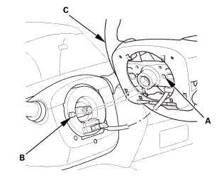
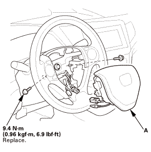
| 2. | Driver's Airbag |
|
|
|
|
|
|
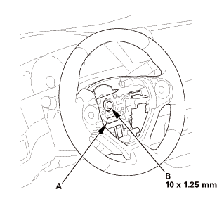
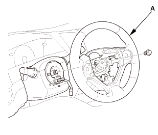
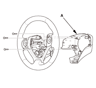
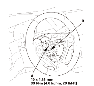
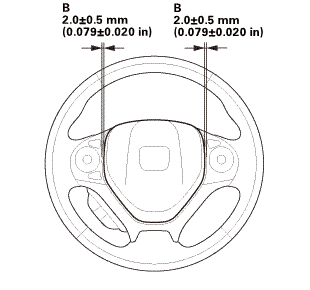
| 3. | Steering Wheel Assembly |
|
|
|
 wxusmm
|
|
|
||||||||||||||||||||

|
|
|
| 4. | Steering Wheel Rear Cover |
|
|
|
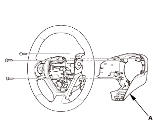
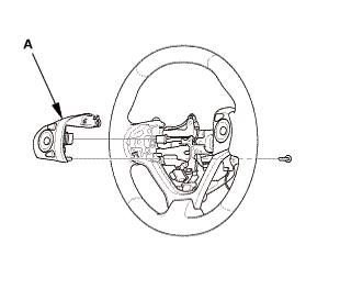
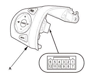
| 5. | Audio Remote/Multi-Information Display Switch |
|
|
|
 Test
Test
| 1. | Audio Remote/Multi-Information Display Switch - Test |
|
|
|
|||||||||||||||||||||||||||||||||||||||

Installation
|
SRS components are located in this area. Review the SRS component locations and the precautions and procedures before doing repairs or service. |
| 1. | Audio Remote/Multi-Information Display Switch |
|
|
|
| 2. | Steering Wheel Rear Cover |
|
|
|
| 3. | Steering Wheel Assembly |
|
|
|
|
|
|
|||||||||
|
|
|
 no
no| 4. | Driver's Airbag |
|
|
|
||||||||||
 mmmmin)in!
|
|
|
||||||||||||

| 5. | Battery Terminal (SRS) - Reconnection |
|
|
|
||||||||||||||||
 (o.2ao.sam.
| 6. | HDS DLC - Connection |
|
|
|

| 7. | VSA Sensor Neutral Position - Memorization |
|
||||||||||
| 8. | Steering Angle Sensor Neutral Position - Clear |
|
|||||||

 Audio Unit Removal and Installation (With Premium Audio)
0101B5
1.
Driver's Dashboard Lower Cover
1.
Remove the driver's dashboard lower cover (A).
...
See also:
Honda Civic Owners Manual. USB Port(s)
Install the iPod USB connector or the USB flash
drive to the front USB port.
Models with color audio system
The USB port (1.0A) is for playing audio
files on a USB flash drive and connecting
a cellular phone and charging device.
Models with Display Audio
The USB port (1.5A) is f ...
